

Explosion proof gas detection systems for oil and gas facilities exist to answer one question before an ignition source becomes relevant: is a flammable concentration forming, and what happens next? The enclosure marking, the sensing principle, the response time and the calibration regime all follow from that question. Most specification failures happen before a purchase order is raised, when a detector list is copied from an earlier project without confirming which gas is present, how it disperses, and what the control system is required to do when the alarm appears. This guide works through the decisions that determine whether an installed system can actually perform that function.
What the Detection Loop Must Prove Before You Buy
A gas detector is a measuring instrument. The safety function is the loop: sensor, transmitter, signal path, logic solver, alarm, and where applicable, shutdown or isolation. Treating the detector as the whole system is the most common specification error on oil and gas projects, because every element in that chain can fail independently and only one of them is certified as a detector.
The starting document is the area classification drawing. IEC 60079-10-1 sets out how releases are assessed and how Zone 0, Zone 1 and Zone 2 are assigned, and detector locations should be traceable to that assessment [1]. If the classification drawing and the detector layout cannot be reconciled, the layout is usually the document that is wrong.
The second document is the performance standard the detector is tested against. IEC 60079-29-1 defines how flammable gas detectors are type tested and what the published performance data actually means [2]. A detector that carries an explosion protection certificate but no performance statement has been certified as safe to install, not as capable of detecting. Those are different claims, and procurement documents frequently merge them.
Where the detection loop performs a safety function, functional safety requirements apply. IEC 61511-1 governs safety instrumented systems in the process industry and requires proof test intervals, diagnostic coverage and systematic capability to be defined before the loop is commissioned [3]. A SIL claim on a datasheet describes a device in a defined configuration. It says nothing about the installation until the proof test regime is written down.
Matching Detection Principle to the Gas
| Principio | What it measures | Suits | Limits to check |
|---|---|---|---|
| Catalytic bead (pellistor) | Heat released by oxidation on a heated bead | %LEL measurement of most hydrocarbon gases | Needs oxygen; poisoned by silicones, lead compounds and some sulphur species; can be inhibited at high concentration |
| Point infrared | Absorption at a gas-specific wavelength | Hydrocarbons in oxygen-deficient or inert atmospheres | Does not respond to hydrogen, acetylene or other gases without an absorption band |
| Open-path infrared | Total absorption across a line of sight | Large areas, fence lines, tank farms | Fog, rain, dust and mechanical movement interrupt the beam |
| Electrochemical | Current from a chemical reaction | Toxic gases such as H2S and CO at low ppm | Limited operating life; temperature sensitive |
| Semiconductor (MOS) | Conductivity change in a heated oxide | General indication in ambient monitoring | Broad cross-sensitivity; poor selectivity |
The table is a screening tool, not a selection. Two questions usually decide the principle. First, does the target gas have an infrared absorption band? Second, will the atmosphere at the detector ever be oxygen deficient, whether through inerting, purging or displacement in a confined space? If the second answer is yes, a catalytic bead detector will under-read or fail, and point infrared becomes the default.
Cross-sensitivity deserves its own line in the specification. A detector’s published gas list is not a guarantee of equal response across that list, and a calibration gas chosen for convenience rather than relevance will produce a repeatable but wrong reading. State the calibration gas, its concentration, and the response factor applied to the target gas.
Reading the Equipment Marking
| Elemento del marcado | What it tells you | Lo que no te dice |
|---|---|---|
| Ex d, Ex e, Ex i, Ex n | Protection concept used to prevent ignition | Detection performance or response time |
| IIA, IIB, IIC | Gas group the equipment is rated for | That the sensor responds equally to every gas in that group |
| T1 to T6 | Maximum surface temperature class | The concentration at which the alarm trips |
| IP66, IP67 | Ingress protection against dust and water | Corrosion resistance in a salt-laden or sour atmosphere |
| Rango de temperatura ambiental | Operating limits of the enclosure | Whether the reading stays accurate across that range |
The most frequent misreading is to treat “Ex d IIC T6” as a performance statement. It is an ignition protection statement. The enclosure contains an internal explosion and quenches the flame path; the temperature class confirms the surface will not exceed the autoignition temperature of the gas group. Neither says anything about how quickly or how accurately the device detects.
In Europe, equipment falls under Directive 2014/34/EU, which requires the manufacturer to declare the category and the conformity assessment route [4]. IECEx operates as a separate international certification scheme, and a project may require both, plus a national approval such as NEC or CNEX depending on the site. A certificate from one scheme is not evidence of approval under another, and the marking on the nameplate is the only reliable statement of what was actually certified.
Placement, Coverage, and Response Time
Detector placement is a dispersion question, not a spacing question. Gas density relative to air is the starting point: methane and hydrogen rise and accumulate at high points, while propane, butane and H2S are heavier and collect in low-lying areas, sumps and pits. Release momentum, ventilation rate and obstructions then modify that basic picture, often substantially. A detector mounted at the ceiling of a well-ventilated compressor house may see nothing from a dense release that disperses at grade.
API RP 505 provides the classification framework used across petroleum facilities for Zone 0, Zone 1 and Zone 2 locations and is a common reference in project specifications [5]. It addresses the electrical installation, not the detection layout, so the layout still needs its own justification.
Response time is where datasheets and reality diverge most. T50 and T90 describe how long the sensor takes to reach 50% and 90% of its final reading after exposure. Those figures drive the shutdown logic: if a detector takes 30 seconds to reach an alarm threshold, a shutdown action timed at 10 seconds is protecting nothing. Ask for the response time at the specified flow rate, not the fastest figure in the catalogue.
Coverage has no reliable square-metre rule. Where a project specifies one detector per fixed area, confirm whether that figure came from a dispersion study, a corporate standard, or a previous project. Only the first is a defensible basis.
Integration: Alarms, Shutdowns, and Control Room Interfaces
The detection loop only becomes useful when the signal reaches something that acts. Signal type is the first decision: 4-20 mA analogue for point-to-point wiring, HART where configuration access is needed, or Modbus and other digital protocols where detector counts make discrete wiring impractical. Each choice changes the cable schedule, the marshalling arrangement and the spare capacity left for future expansion.
Voting logic needs to be agreed in writing. A single detector tripping a full plant shutdown produces nuisance trips that operators eventually bypass, and a bypassed alarm is worse than no alarm because it appears in the cause and effect matrix as functional. Two-out-of-three voting, or a two-stage alarm with a first-stage warning and a second-stage action, is common where process stability matters.
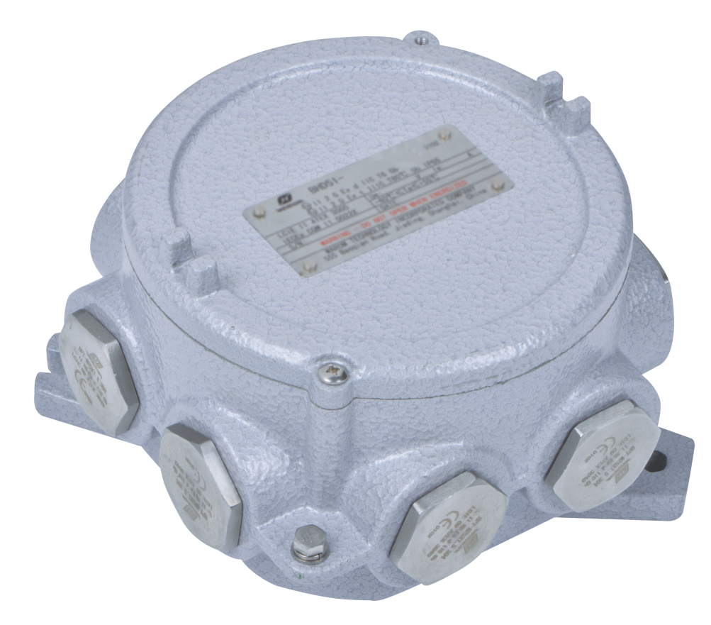
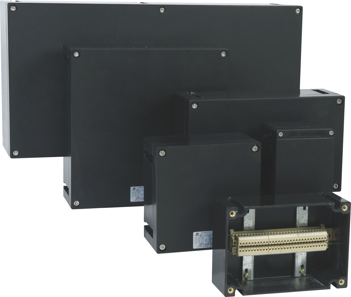
Field wiring hardware deserves the same scrutiny as the detector. Cajas de unión y armarios terminales carry the loop through the hazardous area, and their ingress protection, terminal capacity and cable entry configuration determine whether the installation survives its first wet season.
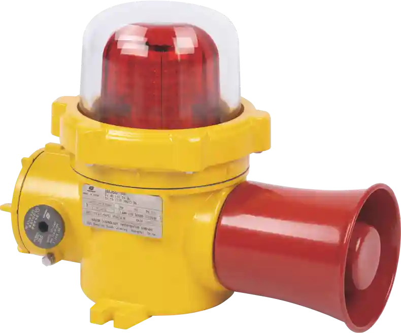
Alarm annunciation is the visible end of the loop. An audio-visual device must be rated for the same gas group and temperature class as the detectors, and its sound pressure level has to be checked against the ambient noise of the process area, not against a quiet office figure.
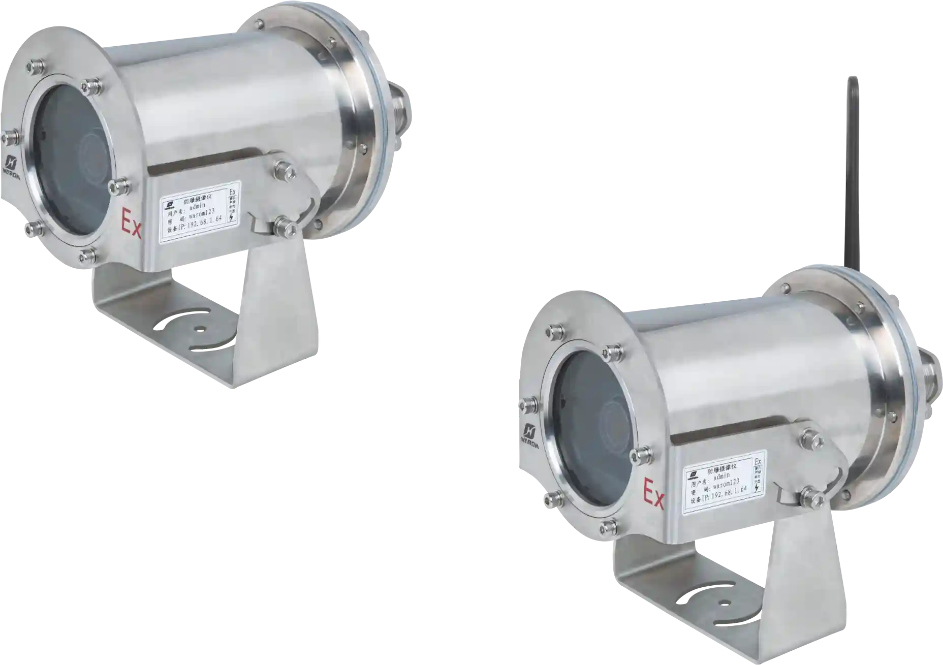
Where the facility also relies on camera surveillance for confirmation of a release, the camera enclosure follows the same classification logic. A monitoring camera rated for Zone 1 does not replace a gas detector, but it shortens the time between alarm and confirmed location.
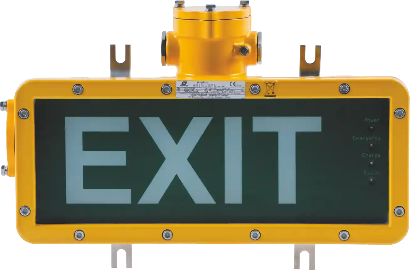
Emergency lighting belongs in the same conversation. When an alarm triggers evacuation, the egress route needs illumination that is itself rated for the area, and that circuit is often forgotten until the commissioning walkdown.
Offshore and export terminals add a second layer of classification and documentation review on top of the onshore case. <Equipo a Prueba de Explosiones: Seguridad y Cumplimiento en las Cubiertas de FPSO> covers how topside safety and compliance requirements are handled for floating production facilities.
RFQ and Acceptance Checklist
| RFQ field | Qué solicitar | Por qué importa |
|---|---|---|
| Target gas and range | Gas name, CAS number, measurement range in %LEL or ppm | Stops a detector being quoted for the wrong gas family |
| Detection principle | Sensor technology and calibration gas | Determines whether the device works in an oxygen-deficient atmosphere |
| Certificación | Scheme, certificate number, marking string, gas group and temperature class | Confirms the equipment is approved for the zone, not just similar to it |
| Response time | T50 and T90 at the specified flow rate | Sets the maximum allowable shutdown delay |
| Output and protocol | 4-20 mA, HART, Modbus, relay contacts | Drives cable schedule and control system interface |
| Entorno | Ambient range, IP rating, enclosure material | Prevents premature failure in coastal, sour or high-temperature service |
| Documentación | Datasheet, certificate, calibration certificate, cause and effect matrix | Provides the evidence package for acceptance and future audits |
Acceptance should be a witnessed sequence, not a document review. Confirm the calibration certificate matches the installed device serial numbers. Confirm the alarm threshold trips the correct output at the correct concentration using calibration gas. Confirm the shutdown action occurs within the response time allowance. Confirm the cause and effect matrix in the control system matches the issued version. A loop that passes a bench test but fails a functional test has not been accepted, regardless of what the paperwork says.
Failure Modes Buyers Should Check First
Sensor poisoning is the classic silent failure. Silicones, leaded compounds and some sulphur species degrade the catalytic bead, and the detector continues to report a plausible reading while losing sensitivity. The only defence is a bump test at defined intervals and a calibration record that shows the response actually changed.
Blocked or contaminated sinter discs cause slow or absent response. Dust, paint overspray and insect ingress are common in outdoor installations, and a detector that reads zero in a known release area should be treated as suspect rather than reassuring.
Moisture ingress follows poor cable entry practice. A junction box with an unused entry left open, or a gland fitted without the correct sealing arrangement, will pass a dry commissioning test and fail within a season.
Wrong calibration gas produces repeatable error. If the cylinder does not match the target gas, every subsequent calibration confirms the same offset. Record the cylinder number and gas concentration against each calibration event.
Bypassed alarms are an organisational failure with technical consequences. Any bypass should be logged, time-limited and reviewed, because an alarm that is permanently inhibited trains operators to ignore the system.
FAQ
Are explosion proof gas detectors the same as intrinsically safe ones?
No. Flameproof (Ex d) equipment contains an internal explosion within a heavy enclosure and quenches the flame path. Intrinsically safe (Ex i) equipment limits the energy entering the hazardous area so that ignition cannot occur, which usually means a lighter device and a barrier or isolator in the safe area. Both can be appropriate, but the choice affects wiring, enclosure weight, maintenance access and the loop’s certified parameters.
How often should a gas detection system be calibrated?
The interval comes from the application, the sensor technology and the manufacturer’s published drift data, not from a universal number. What matters is that the interval is written into the maintenance system, that a bump test confirms response between calibrations, and that any detector failing a bump test is removed from service rather than recalibrated in place and returned to duty without investigation.
Can one detector cover a whole pump room?
Rarely, and the justification should be documented rather than assumed. Coverage depends on the release scenario, ventilation, gas density and obstructions. A single detector may be adequate for a small, well-ventilated space with a defined leak source, but the reasoning needs to be traceable, because a coverage assumption that is never written down cannot be reviewed when the process changes.
What does T3 or T4 mean on a gas detector?
The T class states the maximum surface temperature the equipment will reach in service, expressed as a range that must stay below the autoignition temperature of the surrounding gas. A T4 rating is more restrictive than T3. Selecting a higher T number is not an improvement; it is a different thermal limit, and it must be matched to the actual gas present rather than to the highest number available.
Does an ATEX certificate cover the whole detection system?
No. The certificate covers the equipment described in it, under the conditions stated in it. Cable glands, junction boxes, barriers, alarm devices and the control system each need their own approval, and the system-level assessment is the installer’s or integrator’s responsibility. A project that holds certificates for every component but no system assessment has not demonstrated that the loop is safe.
Specify the Loop, Not the Box
The detector is one component in a chain that only works when every element is matched to the release scenario, the area classification and the required action. Send the area classification drawing, the target gas list with concentrations, the required response time and the intended shutdown action to gm*@***om.com, or call +86 21 39977076 or +86 21 39972657, and the specification can be checked against the loop it has to protect rather than against a catalogue page.
Referencias
[1] IEC 60079-10-1:2020, “Atmósferas explosivas – Parte 10-1: Clasificación de áreas – Atmósferas de gas explosivo”, Comisión Electrotécnica Internacional, 2020.
[2] IEC 60079-29-1:2016, “Explosive atmospheres – Part 29-1: Gas detectors – Performance requirements of detectors for flammable gases,” International Electrotechnical Commission, 2016.
[3] IEC 61511-1:2016, “Functional safety – Safety instrumented systems for the process industry sector – Part 1: Framework, definitions, system, hardware and application programming requirements,” International Electrotechnical Commission, 2016.
[4] Directive 2014/34/EU, “Harmonisation of the laws of the Member States relating to equipment and protective systems intended for use in potentially explosive atmospheres,” European Parliament and Council of the European Union, 2014.
[5] API RP 505, “Recommended Practice for Classification of Locations for Electrical Installations at Petroleum Facilities Classified as Class I, Zone 0, Zone 1, and Zone 2,” American Petroleum Institute, 2018.
Si está interesado, consulte estos artículos relacionados:
Guía definitiva de iluminación portátil a prueba de explosiones
La delegación de compradores internacional de CSSOPE elogió grandemente a “WAROM Intelligent Manufacturing”
Productos a prueba de clima para grúas portuarias: garantizando la fiabilidad marina
Equipo a prueba de explosiones: Salvaguardando los variadores de ventilación de minas
Con más de una década de experiencia, es un Ingeniero Eléctrico a prueba de explosiones con experiencia en el diseño y fabricación de productos de seguridad y a prueba de explosiones. Posee una experiencia profunda en áreas clave que incluyen sistemas a prueba de explosiones, iluminación nuclear, seguridad marina, protección contra incendios y sistemas de control inteligente. En Warom Technology Incorporated Company, ocupa roles de liderazgo dual como Subgerente de Ingeniería para Negocios Internacionales y Jefe del Departamento Internacional de I+D, donde supervisa iniciativas de I+D y garantiza la entrega precisa de la documentación de diseño para proyectos internacionales. Comprometido con avanzar la seguridad industrial global, se enfoca en traducir tecnologías complejas en soluciones prácticas, ayudando a los clientes a implementar sistemas de control más seguros, más inteligentes y fiables en todo el mundo.

Qi Lingyi