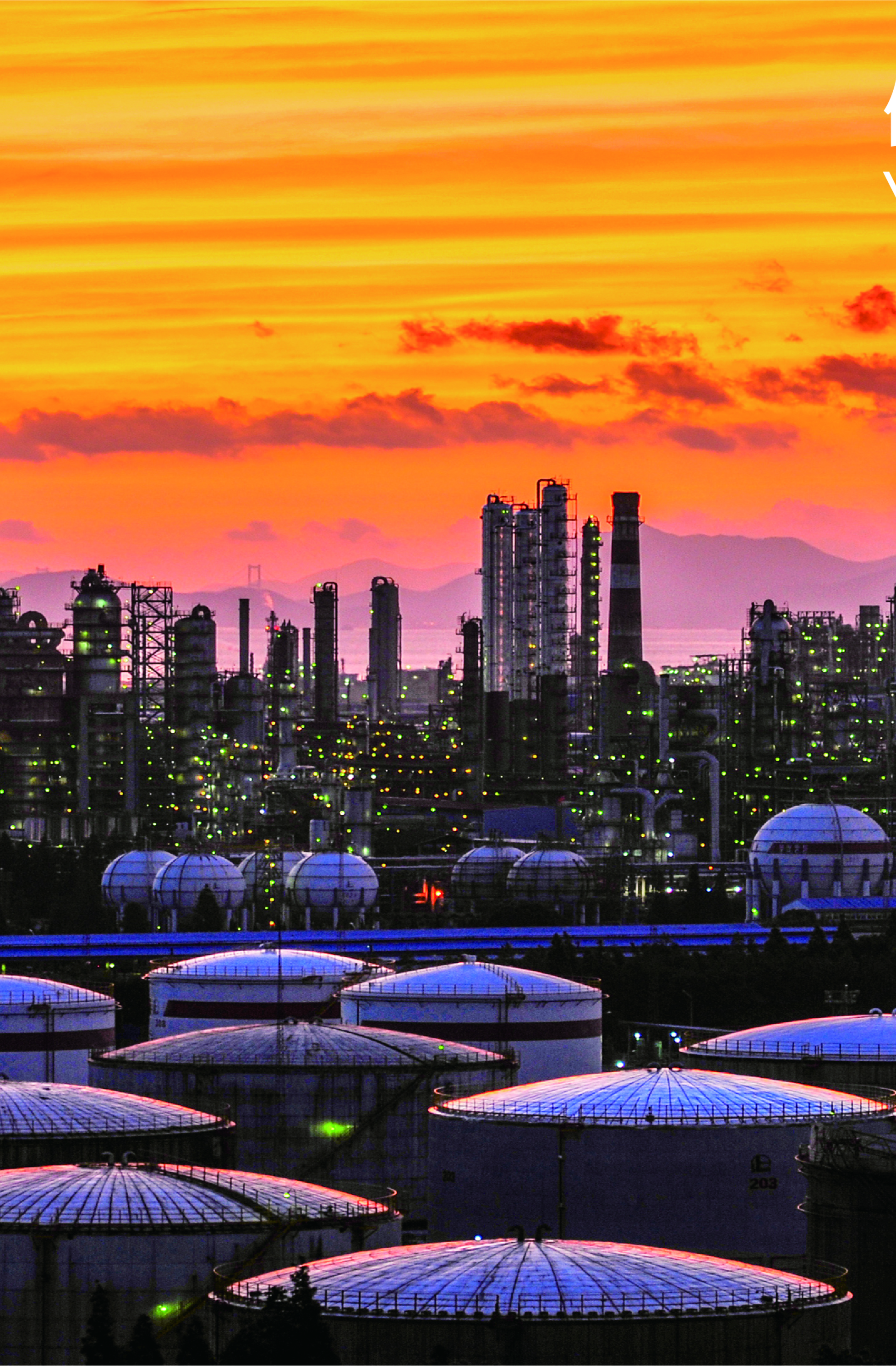
Offshore drilling rigs operate in environments where flammable hydrocarbons are constantly present, and the margin for error on ignition control is effectively zero. The combination of volatile gases, saltwater corrosion, and remote locations means that standard industrial electrical equipment simply cannot be deployed—everything from lighting to junction boxes must be engineered to prevent becoming an ignition source. Zone classifications under IEC 60079 standards determine what protection methods are required in each area of a rig, and getting this wrong has consequences that extend far beyond regulatory fines. The equipment selection process starts with understanding exactly where explosive atmospheres are likely to occur and for how long, then matching protection technologies to those conditions. Projects like Tilenga in Uganda, which included wellpads, a Central Processing Facility, and pipeline infrastructure, demonstrate that zero safety incidents is achievable when hazard classification and equipment certification are handled correctly from the outset.
How Zone Classifications Determine Equipment Requirements on Offshore Rigs
The zone system under IEC 60079 divides hazardous areas based on how frequently an explosive atmosphere is present. Zone 0 locations—inside process vessels and storage tanks—have explosive gas atmospheres present continuously or for extended periods, requiring the highest level of protection. Zone 1 covers areas where explosive atmospheres are likely during normal operations, such as near wellheads and in pump rooms. Zone 2 applies where explosive atmospheres are unlikely under normal conditions or will only persist briefly, including storage areas and ventilation outlets.
| Zone | Likelihood of Explosive Atmosphere | Typical Offshore Locations |
|---|---|---|
| Zone 0 | Continuous or long periods | Inside process vessels, tanks |
| Zone 1 | Likely in normal operation | Near wellheads, pump rooms |
| Zone 2 | Unlikely, or for short periods | Storage areas, ventilation outlets |
The classification directly determines which protection methods are acceptable. Zone 0 equipment must use intrinsic safety or special protection techniques that limit energy below ignition thresholds under all fault conditions. Zone 1 allows flameproof enclosures, increased safety designs, and pressurized systems. Zone 2 permits additional methods including non-sparking equipment. Misclassifying a zone—treating a Zone 1 area as Zone 2, for instance—creates a gap between the actual risk and the protection level, which is precisely the condition that leads to incidents.
The marine environment adds complications that onshore facilities rarely face. Salt spray accelerates corrosion on enclosure seals and cable glands, potentially compromising the integrity of flameproof joints over time. Vibration from drilling operations and wave motion stresses electrical connections continuously. Temperature swings between direct sun exposure and night cooling create condensation inside enclosures unless drainage and breathing devices are properly specified. These factors mean that equipment rated for onshore Zone 1 service may not survive a single season offshore without marine-specific modifications.
What Protection Technologies Actually Do in Explosion-Proof Equipment
Explosion protection is not a single technology but a family of methods, each suited to different equipment types and zone requirements. Understanding what each method actually accomplishes helps in evaluating whether a particular product is appropriate for a specific application.
Intrinsic safety works by limiting the electrical and thermal energy available in a circuit to levels below what can ignite the most easily ignitable mixture of the gases present. This approach is used primarily for instrumentation and control circuits where energy requirements are low. The advantage is that intrinsically safe equipment can be maintained and adjusted in hazardous areas without de-energizing, because the circuit cannot produce a dangerous spark even under fault conditions.
Flameproof enclosures take the opposite approach—they assume an internal explosion may occur and are designed to contain it. The enclosure gaps are engineered so that hot gases escaping after an internal ignition cool below the ignition temperature of the external atmosphere before they exit. This method is common for motors, junction boxes, and lighting fixtures where the energy levels are too high for intrinsic safety.
Pressurized enclosures maintain a positive pressure of clean air or inert gas inside, preventing flammable gases from entering. This method is often used for control panels and analyzer houses where the equipment inside is not inherently explosion-proof but can be protected by excluding the hazardous atmosphere entirely.
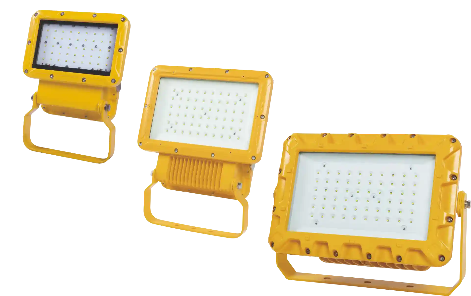
The BAT86 Explosion-proof LED Floodlights illustrate how these principles translate into actual products. The steel lamp body with powder-coated surface and IP66 protection addresses both the explosion containment requirement and the environmental durability needed offshore. LED technology reduces heat generation compared to older lighting technologies, which matters because surface temperature limits are part of the certification requirements—equipment must not create hot surfaces that could ignite gas mixtures even without a spark.
Why Dual ATEX and IECEx Certification Matters for Equipment Selection
ATEX certification is a European Union requirement—equipment sold for use in potentially explosive atmospheres within the EU must carry ATEX marking. IECEx is an international certification scheme that provides a standardized approach to conformity assessment, accepted in countries that have adopted the IEC 60079 series of standards. The two systems assess essentially the same technical requirements, but through different administrative frameworks.
For offshore operators, the practical significance is that equipment with only ATEX certification may face additional documentation requirements or testing when deployed outside EU waters. Equipment with both certifications—like the BCZ8060 Series Explosion-proof Plugs and Sockets—can be deployed across multiple jurisdictions without re-certification, which simplifies procurement and reduces the risk of compliance gaps when rigs move between operating areas.
The certification process itself involves third-party testing and factory audits. Certified products are tested to verify that protection methods function as designed under fault conditions, that temperature ratings are accurate, and that manufacturing quality control maintains consistency. The certificate number and marking on equipment provide traceability back to the test reports, which becomes relevant during incident investigations or regulatory inspections.
One point that sometimes gets overlooked: certification applies to the complete assembly, not just individual components. A flameproof junction box loses its certification if fitted with cable glands that were not tested as part of the original certification or explicitly approved for use with that enclosure. This is why equipment suppliers provide specific lists of compatible accessories, and why substituting components in the field can create compliance problems even when the substitute appears technically equivalent.
How Offshore Conditions Affect Electrical System Design and Material Selection
The combination of saltwater exposure, temperature extremes, and continuous vibration creates conditions that would destroy standard industrial electrical equipment within months. Material selection and construction details that might be optional onshore become mandatory offshore.
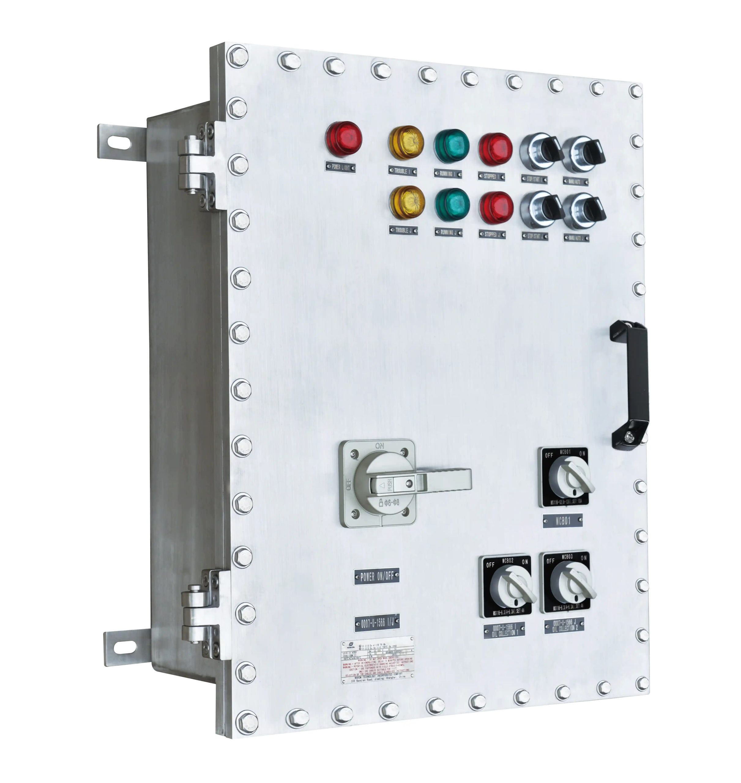
Copper-free aluminum alloys are specified for enclosures because copper accelerates galvanic corrosion when combined with aluminum in a saltwater environment. The HRMD92 Series Explosion Proof Distribution Panels use this material specifically to avoid the corrosion cells that would form at copper-aluminum interfaces. Stainless steel fasteners are similarly specified to prevent the rust staining and eventual failure that would occur with zinc-plated hardware.
IP66 ratings indicate that enclosures are dust-tight and protected against powerful water jets—relevant when equipment is exposed to wave spray or deck washdown operations. The rating system goes higher (IP67 for temporary immersion, IP68 for continuous immersion), but IP66 is the practical minimum for exposed deck equipment.
Temperature ratings deserve attention because offshore locations span from arctic drilling operations to tropical waters. The HRMD92 panels are rated for -60°C to +60°C ambient temperature, which covers essentially all operating environments. Equipment specified with narrower temperature ranges may require supplemental heating or cooling systems, adding complexity and potential failure points.
The General Paint project demonstrated how these considerations apply in practice. Customizing explosion-proof junction and distribution boxes for integration into the customer’s procurement system required matching not just the electrical specifications but also the material grades and surface treatments to the expected service environment. This kind of integration work—ensuring that explosion-proof equipment interfaces correctly with the broader electrical system—is where many projects encounter difficulties if the supplier lacks experience with the specific application.
What Installation and Maintenance Practices Preserve Certification Integrity
Explosion-proof equipment arrives from the factory with certification based on specific assembly conditions. Maintaining that certification throughout the equipment’s service life requires installation and maintenance practices that preserve the protection method’s integrity.
For flameproof enclosures, the critical dimension is the flame path—the gap between mating surfaces through which gases must travel to escape after an internal ignition. These surfaces must remain clean, undamaged, and properly lubricated with approved compounds. A scratch across a flame path surface, or contamination with debris that prevents proper seating, can compromise the enclosure’s ability to contain an explosion. Installation procedures specify torque values for cover bolts because under-tightening allows gaps to open under internal pressure, while over-tightening can distort sealing surfaces.
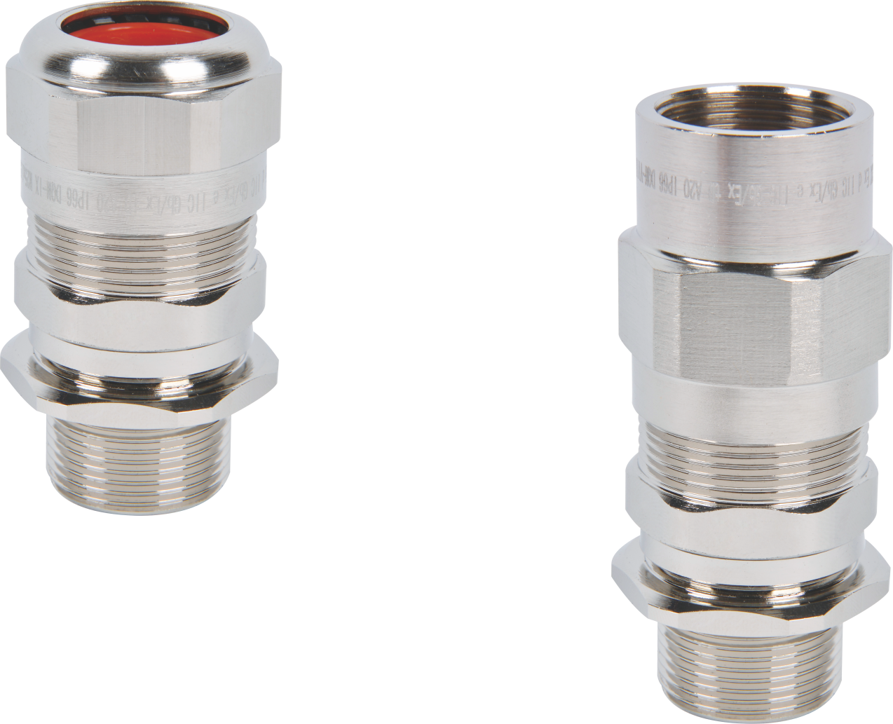
Cable entry points are common failure locations. Cable glands must be the correct type for the cable diameter and construction, properly tightened, and fitted with the sealing elements in the correct orientation. Unused entries must be closed with certified stopping plugs, not improvised covers. The DQM-III&I Cable Glands for unarmored cables with compound barrier illustrate the level of specificity required—these are not generic fittings but components tested and certified for use with specific enclosure types and cable specifications.
 Preventative maintenance schedules for offshore explosion-proof equipment typically include visual inspection of enclosure surfaces and seals, verification of cable gland tightness, functional testing of safety interlocks, and documentation of any repairs or component replacements. The inspection frequency depends on the zone classification and the operating environment severity, but quarterly visual inspections and annual detailed inspections are common baselines.
The Fushilai Pharmaceutical project, while not offshore, demonstrated the coordination required for phased equipment delivery aligned with construction progress. Offshore projects face similar scheduling challenges, complicated by weather windows for installation and the logistics of transporting equipment to remote platforms. Equipment that arrives damaged or with missing components creates delays that can cascade through the project schedule.
Where Offshore Drilling Conditions Create Unique Equipment Demands
Offshore drilling rigs combine hazardous area requirements with environmental conditions that few other industrial settings match. The equipment must handle explosive atmosphere risks while simultaneously surviving conditions that would destroy equipment designed only for hazardous area service without marine hardening.
Weather exposure is continuous and extreme. Equipment on open decks faces direct sunlight, driving rain, salt spray, and temperature swings that can exceed 40°C within a single day in some locations. Helideck lighting, like the HDL-C Helideck Explosion-proof Light, must maintain visibility for aircraft operations while withstanding these conditions and meeting the explosion protection requirements for the surrounding hazardous zones.
Remote location means that equipment failures have consequences beyond the immediate repair cost. A failed floodlight on an onshore facility is an inconvenience; a failed floodlight on an offshore platform during night operations can halt work until replacement equipment arrives, potentially days later depending on weather and logistics. This drives the emphasis on reliability and redundancy in offshore electrical system design.
Vibration from drilling operations, wave motion, and helicopter operations creates fatigue stresses on electrical connections and mounting hardware. Equipment designed for static industrial installations may experience loosening of terminals, cracking of rigid conduit connections, or failure of mounting brackets when subjected to continuous vibration. Marine-rated equipment addresses this through flexible connections, vibration-resistant terminal designs, and mounting systems that accommodate movement.
The Tilenga project experience—supplying explosion-proof lighting and electrical systems with zero safety incidents despite extreme site conditions—demonstrates that these challenges are manageable with appropriate equipment selection and installation practices. The key is recognizing that offshore hazardous area equipment must satisfy two overlapping but distinct requirement sets: the explosion protection standards and the marine environmental durability requirements.
If your offshore project involves hazardous area electrical systems, discussing the specific zone classifications and environmental conditions early in the design phase helps ensure that equipment specifications address both the explosion protection and durability requirements. For consultation on equipment selection or custom solutions, contact WAROM TECHNOLOGY at gm*@***om.com or +86 21 39977076.
Frequently Asked Questions
What distinguishes ATEX certification from IECEx certification for offshore explosion-proof equipment?
ATEX is a European Union directive that applies to equipment placed on the EU market for use in potentially explosive atmospheres. IECEx is an international certification scheme based on IEC standards, accepted by countries that have adopted those standards into their national regulatory frameworks. The technical requirements are largely equivalent—both assess explosion protection methods against the same underlying engineering principles. The practical difference is administrative: ATEX certification is mandatory for EU deployment, while IECEx provides a pathway for international acceptance without country-by-country re-certification. Equipment carrying both certifications, such as the BCZ8060 Series plugs and sockets, can be deployed across multiple regulatory jurisdictions without additional testing or documentation, which simplifies procurement for operators with assets in different regions.
How do operators maintain explosion-proof electrical system reliability in corrosive offshore environments?
Long-term reliability starts with material selection—copper-free aluminum alloys for enclosures, stainless steel fasteners, and powder-coated or otherwise protected surfaces. IP66 or higher ingress protection prevents salt spray and washdown water from entering enclosures. Beyond initial specification, sustained reliability requires inspection and maintenance programs that check enclosure seals, cable gland tightness, and flame path surface condition at regular intervals. Corrosion that compromises a flameproof joint or allows water ingress into an enclosure can develop between inspections, so the inspection frequency must match the corrosion rate in the specific operating environment. Replacing components before they fail—rather than running to failure—is standard practice for safety-critical equipment offshore.
How does risk assessment inform explosion-proof equipment selection for offshore drilling rigs?
Risk assessment identifies which areas of a rig fall into each zone classification, what gas groups and temperature classes apply, and what environmental conditions the equipment must withstand. This information determines the minimum protection level required in each location and the specific certification markings that equipment must carry. A thorough assessment also identifies installation constraints—available space, cable routing, access for maintenance—that affect which equipment configurations are practical. The assessment output is essentially a specification document that equipment suppliers use to propose appropriate products. Skipping or shortcutting the assessment phase leads to equipment that is either over-specified (adding unnecessary cost) or under-specified (creating compliance gaps and safety risks). For projects involving multiple hazardous zones and varying environmental exposures, working with suppliers who can review the assessment and recommend equipment across the full range of conditions helps ensure consistency.
If you’re interested, you may want to read the following articles:
Warom at OIL&GAS INDONESIA
Warom Technology “International IECEx explosion-proof technology Thailand special symposium” was successfully held
With over a decade of experience, he is a seasoned Explosion-Proof Electrical Engineer specializing in the design and manufacture of safety and explosion-proof products. He possesses in-depth expertise across key areas including explosion-proof systems, nuclear power lighting, marine safety, fire protection, and intelligent control systems. At Warom Technology Incorporated Company, he holds dual leadership roles as Deputy Chief Engineer for International Business and Head of the International R&D Department, where he oversees R&D initiatives and ensures the precise delivery of design documentation for international projects. Committed to advancing global industrial safety, he focuses on translating complex technologies into practical solutions, helping clients implement safer, smarter, and more reliable control systems worldwide.
Qi Lingyi