Industrial facilities handling flammable substances face a fundamental challenge: how do you run electrical systems in spaces where a single spark could trigger catastrophe? The answer lies in explosion proof wiring—specialized electrical infrastructure designed to contain or isolate potential ignition sources before they can interact with explosive atmospheres. Getting this right demands more than following a checklist. It requires understanding how classification systems work, why certain protection methods suit specific applications, and where installations commonly fail despite good intentions. The stakes are straightforward: proper explosion proof wiring prevents fires and explosions; improper wiring creates the conditions for them.
Why Hazardous Area Classification Determines Everything Else in Explosion Proof Wiring
Before selecting a single cable gland or junction box, the classification of the hazardous area must be established. This step shapes every subsequent decision about explosion proof wiring, from equipment ratings to installation methods.
Two classification systems dominate global practice. The Zone system, used internationally under IECEx and ATEX frameworks, categorizes areas based on how often and how long an explosive atmosphere is present. For gases and vapors, Zone 0 indicates continuous presence, Zone 1 covers likely presence during normal operation, and Zone 2 applies when presence occurs only under abnormal conditions for short periods. Combustible dusts follow parallel logic with Zone 20, Zone 21, and Zone 22. The Division system, standard in North America under the National Electrical Code, takes a different approach. It groups hazardous locations into Class I (flammable gases or vapors), Class II (combustible dusts), and Class III (ignitable fibers or flyings), then subdivides each into Division 1 (likely presence) and Division 2 (unlikely presence).
The practical difference between these systems matters when specifying equipment. A Zone 1 area and a Class I, Division 1 area present similar risk profiles, but the certification marks, testing protocols, and acceptable wiring methods differ. Projects spanning multiple jurisdictions often require equipment certified to both systems.
Classification accuracy directly correlates with safety outcomes. The Tilenga oil field development in Uganda illustrates this point. The project included wellpads, a Central Processing Facility, and pipelines, some running through Murchison Falls National Park. Thorough classification of each area ensured that explosion proof lighting and electrical systems matched the actual hazard levels present. The result was zero safety incidents across the installation, a direct consequence of getting the classification right from the start.
| Classification System | Basis of Classification | Gas/Vapor Zones | Dust Zones | Typical Application |
|---|---|---|---|---|
| Zone System | Frequency/Duration | 0, 1, 2 | 20, 21, 22 | International |
| Division System | Likelihood/Presence | Class I, Div 1, 2 | Class II, Div 1, 2 | North America |
Beyond the classification system itself, the properties of specific hazardous materials shape equipment selection. Flash point, autoignition temperature, and explosive limits determine the gas or dust group and temperature class required. A facility processing hydrogen (Group IIC) needs different equipment specifications than one handling propane (Group IIA). Hydrogen’s wider flammable range and lower ignition energy demand more stringent protection.
The classification process follows a logical sequence: identify potential release sources for flammable substances, determine the type and properties of each hazardous material, assess the likelihood and duration of explosive atmosphere formation, delineate hazardous area boundaries based on ventilation and other factors, then select equipment and wiring methods certified for the resulting classification. Skipping steps or making assumptions introduces risk that no amount of quality equipment can compensate for.
How NEC, ATEX, and IECEx Standards Shape Explosion Proof Wiring Requirements
Compliance with electrical installation codes is not optional in hazardous environments. The three dominant frameworks—NEC in North America, ATEX in the European Union, and IECEx internationally—each impose specific requirements for explosion proof wiring, equipment certification, and installation practices.
The NEC (NFPA 70) provides prescriptive requirements based on the Class and Division system. It specifies acceptable wiring methods, equipment types, and installation details for each classification. In Class I, Division 1 locations, for example, rigid metal conduit or intermediate metal conduit with explosion-proof fittings is typically required. The code leaves relatively little to interpretation, which simplifies compliance but can limit flexibility.
ATEX directives take a different approach. These EU regulations cover both product safety and workplace safety for equipment used in potentially explosive atmospheres. Rather than prescribing specific methods, ATEX establishes essential health and safety requirements that equipment must meet. Manufacturers must conduct conformity assessments and obtain certification from a Notified Body. Users bear responsibility for ensuring safe installation and maintenance. The risk-based philosophy gives more latitude in how requirements are met, but demands greater technical judgment.
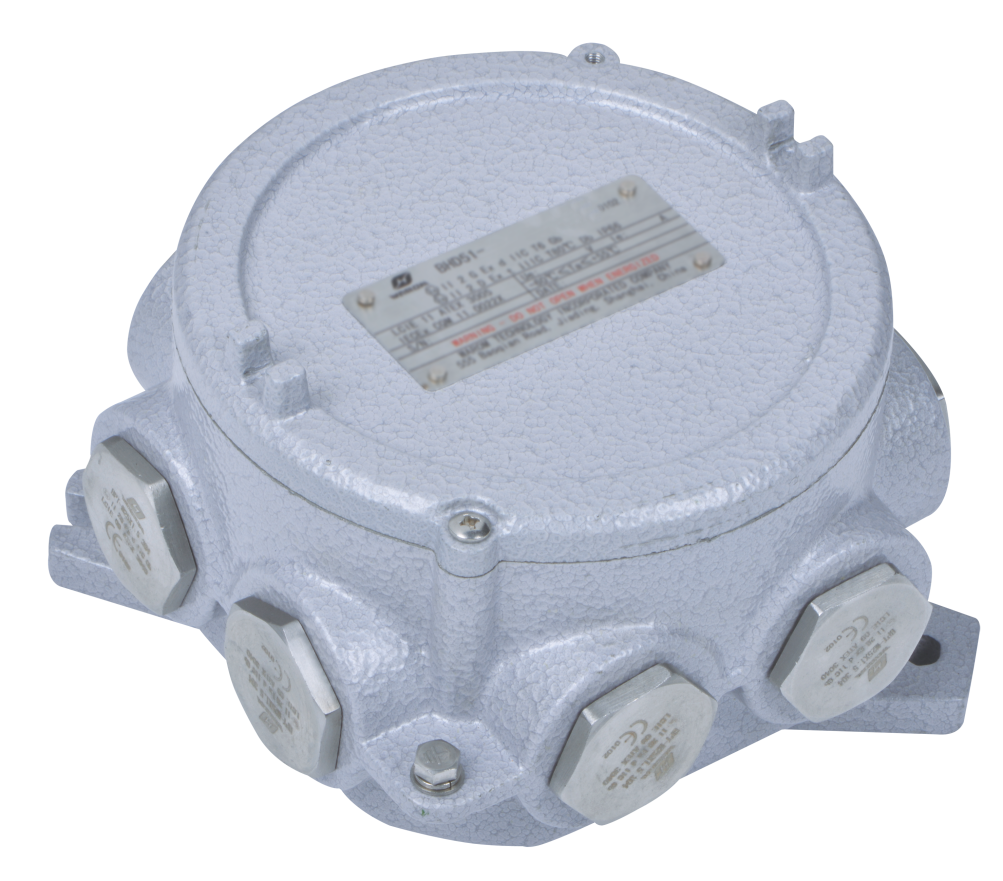
The IECEx scheme aims to harmonize standards globally. It provides an international certification system that can streamline approval processes across multiple countries. A single IECEx certificate of conformity can serve as the basis for obtaining national certifications, reducing duplication of testing and documentation. For projects operating across borders, this efficiency matters. Products like the BHD91 Series Explosion-proof Junction Boxes carry IECEx and ATEX certifications, enabling deployment in diverse international markets without separate certification processes for each jurisdiction.
The practical implications of these standards emerge in project execution. The Fushilai Pharmaceutical facility, focused on international export of APIs and intermediates, required explosion-proof distribution boxes for workshops, warehouses, tank farms, and pump controls. All equipment needed certifications acceptable in the company’s export markets. Early coordination with design institutes and project owners ensured that compliance requirements were identified before procurement, avoiding delays from equipment that met one standard but not another.
| Feature | NEC (North America) | ATEX (European Union) | IECEx (International) |
|---|---|---|---|
| Classification | Class/Division | Zone | Zone |
| Approach | Prescriptive | Directive (Risk-based) | Harmonized (Certification) |
| Certification | NRTL (e.g., UL, FM) | Notified Body | IECEx Certification Body |
| Scope | Electrical Installations | Equipment & Workplace | Equipment |
Certification marks to look for include UL, CCS, BV, LCIE, PTB, Nemko, and DNV. Equipment carrying multiple certifications provides flexibility for facilities that may need to meet different regulatory requirements as operations evolve or expand geographically.
Which Protection Methods Work Best for Different Control Equipment Applications
Selecting the right explosion protection technique depends on the specific application, the hazardous area classification, and practical constraints like power requirements and maintenance access. Several protection methods have established track records in industrial settings.
Intrinsic safety (Ex i) limits electrical and thermal energy within a circuit to levels below ignition thresholds. This approach works well for instrumentation and control signals where power requirements are modest. Intrinsic safety barriers installed between safe and hazardous areas restrict energy transfer, ensuring that even a fault condition cannot release enough energy to cause ignition. The method’s simplicity makes it attractive for sensor networks and low-power control loops.
Flameproof enclosures (Ex d) take a different approach. The electrical equipment sits inside an enclosure engineered to contain any internal explosion and prevent flame propagation to the surrounding atmosphere. This method requires robust construction, proper sealing, and appropriate cable entry systems. The DQM-III/II Series Explosion Proof Cable Glands, certified for Ex db IIC Gb, maintain the integrity of flameproof enclosures when armored cables enter. A compromised cable entry defeats the entire protection concept, making proper gland selection and installation critical.
Purged and pressurized enclosures (Ex p) maintain positive pressure using inert gas or clean air to prevent hazardous substances from entering. This method suits larger control panels or motors where other protection methods would be impractical. The pressurization system requires monitoring to ensure the protective atmosphere is maintained during operation.
Non-incendive wiring (Ex nA) applies where equipment, under normal operating conditions, does not produce arcs, sparks, or hot surfaces capable of ignition. This simpler form of protection suits Division 2 or Zone 2 applications where hazardous atmospheres are present only under abnormal conditions.
The General Paint facility upgrade in Mexico demonstrates how these methods combine in practice. The project addressed serious electrical safety hazards by implementing gas detectors, explosion-proof plugs, junction boxes, and distribution boxes. BHD91 Series Explosion-proof Junction Boxes, constructed from high-strength copper-free aluminum alloy with IP66 ratings, provided corrosion resistance suited to the chemical environment. BCZ8060 Series Explosion-proof Plugs and Sockets, made from GRP composite material, incorporated interlocking switches that prevent connection or disconnection under load. If your facility faces similar challenges with aging electrical infrastructure in hazardous areas, a detailed assessment of current conditions against applicable standards can identify the most cost-effective upgrade path.
What Installation Practices Prevent the Most Common Explosion Proof Wiring Failures
Even properly specified explosion-proof equipment can fail to protect if installation practices fall short. The gap between equipment capability and actual safety performance often comes down to execution details.
Grounding and bonding form the foundation of safe operation in hazardous locations. All metallic components must be effectively bonded to a common grounding system, eliminating potential differences that could generate sparks. Static electricity buildup poses particular risk in dry environments or where materials move through pipes and conveyors. Fault currents must have a clear path to ground to prevent dangerous voltage potentials from developing on equipment enclosures.
Sealing and cable entry integrity require sustained attention. Explosion-proof cable glands must be correctly sized for the cable diameter, properly tightened to manufacturer specifications, and inspected for damage before installation. Over-tightening can damage the cable jacket or the gland itself; under-tightening leaves gaps that compromise the seal. Where sealing compounds are required in conduit systems, they must be properly mixed, applied, and cured according to manufacturer instructions. A rushed installation that skips proper curing time creates a weak point that may not fail immediately but will degrade over time.

Regular inspection catches degradation before it becomes dangerous. Visual checks should identify corrosion, loose connections, damaged enclosures, and compromised seals. Electrical testing verifies that protective devices function as designed. The inspection frequency should match the severity of the environment and the consequences of failure. Facilities with aggressive atmospheres or critical processes typically require more frequent inspection than those with milder conditions.
The Tilenga project in Uganda specified explosion-proof lighting and electrical systems designed for reliability under extreme conditions, including high temperatures, humidity, and remote locations with limited maintenance access. Equipment selection emphasized energy efficiency and low maintenance requirements, recognizing that sustained performance depends on realistic maintenance capabilities. A maintenance program that looks good on paper but cannot be executed in practice provides false assurance.
Where Explosion Proof Wiring Installations Most Often Go Wrong
Several failure patterns appear repeatedly across industries and geographies. Recognizing these patterns helps focus attention where it matters most.
Improper sealing of conduit entries or cable glands ranks among the most common failures. When seals are not correctly installed or maintained, a flame path can form, allowing an internal explosion to propagate to the hazardous atmosphere outside the enclosure. The failure mode is insidious because the equipment may appear functional and pass casual inspection while lacking the protection it was designed to provide.
Using non-certified or incorrectly rated equipment for the specific hazardous area classification directly compromises safety. This error sometimes results from procurement shortcuts, where standard components are substituted for explosion-proof counterparts to save cost or meet delivery schedules. It also occurs when area classifications change due to process modifications, but equipment is not upgraded to match.
Inadequate grounding and bonding create conditions for static discharge or fault-related sparks. These failures often trace back to installation practices rather than design, with connections that were never properly made or have degraded over time.
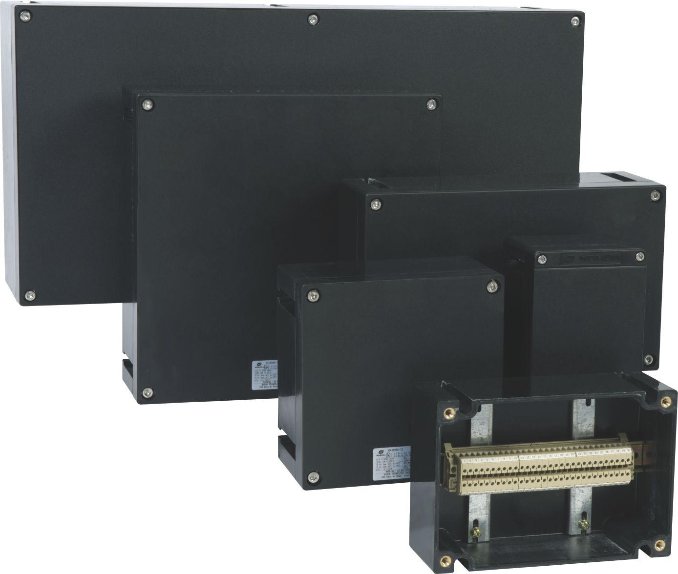
The General Paint facility in Mexico illustrates how comprehensive solutions address multiple risk factors simultaneously. The upgrade included gas detectors, explosion-proof plugs, junction and distribution boxes, static electricity discharge devices, and anti-corrosion equipment. BXM(D)8050 Explosion-proof Illumination Distribution Boxes, with their compound design combining flameproof (Ex d) and increased safety (Ex e) chambers, provided flexible protection suited to the facility’s varied requirements. Anti-static coatings and anti-loosening fasteners addressed specific failure modes identified during the initial assessment.
Frequently Asked Questions About Explosion Proof Wiring
What is the primary purpose of explosion-proof control equipment wiring?
The primary purpose is preventing ignition of flammable gases, vapors, dusts, or fibers in hazardous locations by containing sparks, arcs, or hot surfaces within electrical equipment. This protection extends to both normal operation and fault conditions. The equipment must either prevent ignition sources from forming or isolate them from the hazardous atmosphere.
How does intrinsic safety differ from other explosion protection methods for wiring?
Intrinsic safety limits electrical and thermal energy within a circuit to levels that cannot cause ignition, making it suitable for low-power instrumentation and control signals. Flameproof enclosures contain explosions rather than preventing them. Purged systems prevent hazardous atmosphere ingress through positive pressure. The fundamental difference is that intrinsic safety ensures insufficient energy for ignition exists, while other methods manage the consequences if ignition energy is present.
Are explosion-proof cable glands and conduits always necessary for hazardous area wiring?
Cable glands and conduits are necessary components for maintaining explosion protection integrity. Cable glands create flameproof or dust-tight seals where cables enter enclosures. Conduits protect wiring and can form part of a flameproof system depending on the hazardous area classification and protection method. The specific requirements vary by classification and protection concept, but the function of maintaining enclosure integrity is always critical.
What role does proper grounding and bonding play in explosion-proof electrical systems?
Grounding and bonding dissipate fault currents safely and prevent static electricity buildup. Without proper grounding, fault currents may create dangerous voltage potentials on equipment enclosures. Without proper bonding, potential differences between metallic components can generate sparks. Both conditions create ignition sources that defeat the purpose of explosion-proof equipment. Compliance with NEC and ATEX grounding requirements is a baseline, not an optional enhancement.
How do I determine the correct hazardous area classification for my industrial facility’s electrical systems?
Start by identifying all flammable materials present and their physical properties, including flash point, autoignition temperature, and explosive limits. Evaluate the likelihood and duration of these substances forming explosive atmospheres, considering ventilation, process containment, and operational procedures. Apply the relevant standard (NEC Class/Division or Zone system) to delineate classified areas. The classification determines equipment ratings, wiring methods, and installation requirements for each area.
What are the common pitfalls in wiring explosion-proof control equipment and how can they be avoided?
Common pitfalls include improper sealing of cable entries, using non-certified equipment, inadequate grounding, and incorrect cable gland installation. Avoidance requires certified personnel trained in explosion-proof wiring practices, strict adherence to manufacturer instructions and applicable standards, thorough pre-commissioning verification, and ongoing inspection programs. Equipment should come from manufacturers with appropriate certifications and documented quality systems. To discuss specific requirements for your facility, contact WAROM TECHNOLOGY at gm*@***om.com or +86 21 39977076.
If you’re interested, you may want to read the following articles:
Day 2 of Australian Energy Producers Conference & Exhibition 2025
Warom at HANNOVER MESSE 2025
OSHA Guide: Essential Construction Site Lighting Compliance
WAROM at Australian Energy Producers Conference &Exhibition 2026
WAROM at MARINTEC CHINA 2025
With over a decade of experience, he is a seasoned Explosion-Proof Electrical Engineer specializing in the design and manufacture of safety and explosion-proof products. He possesses in-depth expertise across key areas including explosion-proof systems, nuclear power lighting, marine safety, fire protection, and intelligent control systems. At Warom Technology Incorporated Company, he holds dual leadership roles as Deputy Chief Engineer for International Business and Head of the International R&D Department, where he oversees R&D initiatives and ensures the precise delivery of design documentation for international projects. Committed to advancing global industrial safety, he focuses on translating complex technologies into practical solutions, helping clients implement safer, smarter, and more reliable control systems worldwide.
Qi Lingyi