
Choosing how cables enter an explosion-proof distribution box is one of those decisions that looks straightforward on paper but gets complicated fast once you factor in the actual site conditions. Cable glands and conduit systems both do the job—sealing the enclosure, protecting the cable, maintaining the flameproof rating—but they solve different problems, and picking the wrong one costs time and money during installation or, worse, during an inspection years later.
This piece walks through what actually matters when making that choice: the protection concepts involved, where each method works best, and the tradeoffs that show up in real projects.
What Cable Entries Actually Do in a Flameproof Enclosure
The basic job is simple enough: get the cable into the box without breaking the explosion protection. But “breaking the protection” can happen in several ways that are not always obvious.
A flameproof enclosure (Ex d) is designed to contain an internal explosion and cool the escaping gases enough that they cannot ignite the external atmosphere. The cable entry has to maintain that containment. If gases can migrate through the cable itself—traveling along the spaces between conductors—the enclosure’s flameproof rating means nothing. This is why barrier glands exist: they seal around each individual conductor, not just the outer sheath.
For intrinsically safe circuits (Ex i), the concern shifts. The energy levels are already too low to cause ignition, so the cable entry’s main job is maintaining the circuit’s integrity and preventing faults that could introduce higher energy. The sealing requirements are different, and the gland selection follows different logic.
Dust environments (Ex t) add another layer. Here, the enclosure prevents dust ingress and limits surface temperatures. Cable entries need to maintain the IP rating—typically IP66 or higher—while also ensuring no gap exists where dust could accumulate and eventually ignite from heat buildup.
| Zone | Gas/Vapor Presence | Dust Presence |
|---|---|---|
| 0 | Continuous | Continuous |
| 1 | Likely during normal operation | Likely during normal operation |
| 2 | Unlikely, short duration | Unlikely, short duration |
The zone classification drives everything else. A Zone 1 gas environment demands different rigor than Zone 2, and the cable entry selection has to match.
How Barrier Glands Actually Work and Where They Make Sense
Barrier glands look like regular cable glands from the outside, but the internal design is fundamentally different. After the cable is inserted and the compression seal tightens around the outer sheath, a setting compound is poured into the gland body. This compound flows around and between the individual conductors, then cures to form a solid seal that blocks gas migration through the cable.
This matters because many industrial cables have air gaps between conductors. In a standard compression gland, those gaps remain open pathways. If a flammable gas enters the enclosure through the cable and an internal spark occurs, the explosion can propagate back out through those same gaps—defeating the entire purpose of the flameproof enclosure.
The DQM-III/II Series glands we use on most projects are rated for ambient temperatures from -60°C to +90°C, which covers the majority of industrial applications. The IECEx and ATEX certifications mean the design has been tested and verified to maintain the flameproof concept under fault conditions.
The practical advantage of barrier glands is flexibility. They accommodate a range of cable diameters within each size, handle armored and unarmored cables with different insert configurations, and install relatively quickly once the installer knows the compound curing requirements. For a distribution box with multiple cable entries of varying sizes, glands often make more sense than running conduit to each entry point.
The limitation is that the protection stops at the gland. The cable run between the gland and the previous enclosure or junction box is exposed to whatever mechanical hazards exist in the environment. In a clean control room, this is not a concern. In a process area with forklifts, falling tools, and thermal cycling, it might be.
What IP Rating Do Cable Entries Need in Zone 1?
For Zone 1 gas environments, IP66 is the typical minimum—protection against powerful water jets and complete dust exclusion. IP67 adds protection against temporary immersion, which matters in washdown areas or locations where flooding is possible.
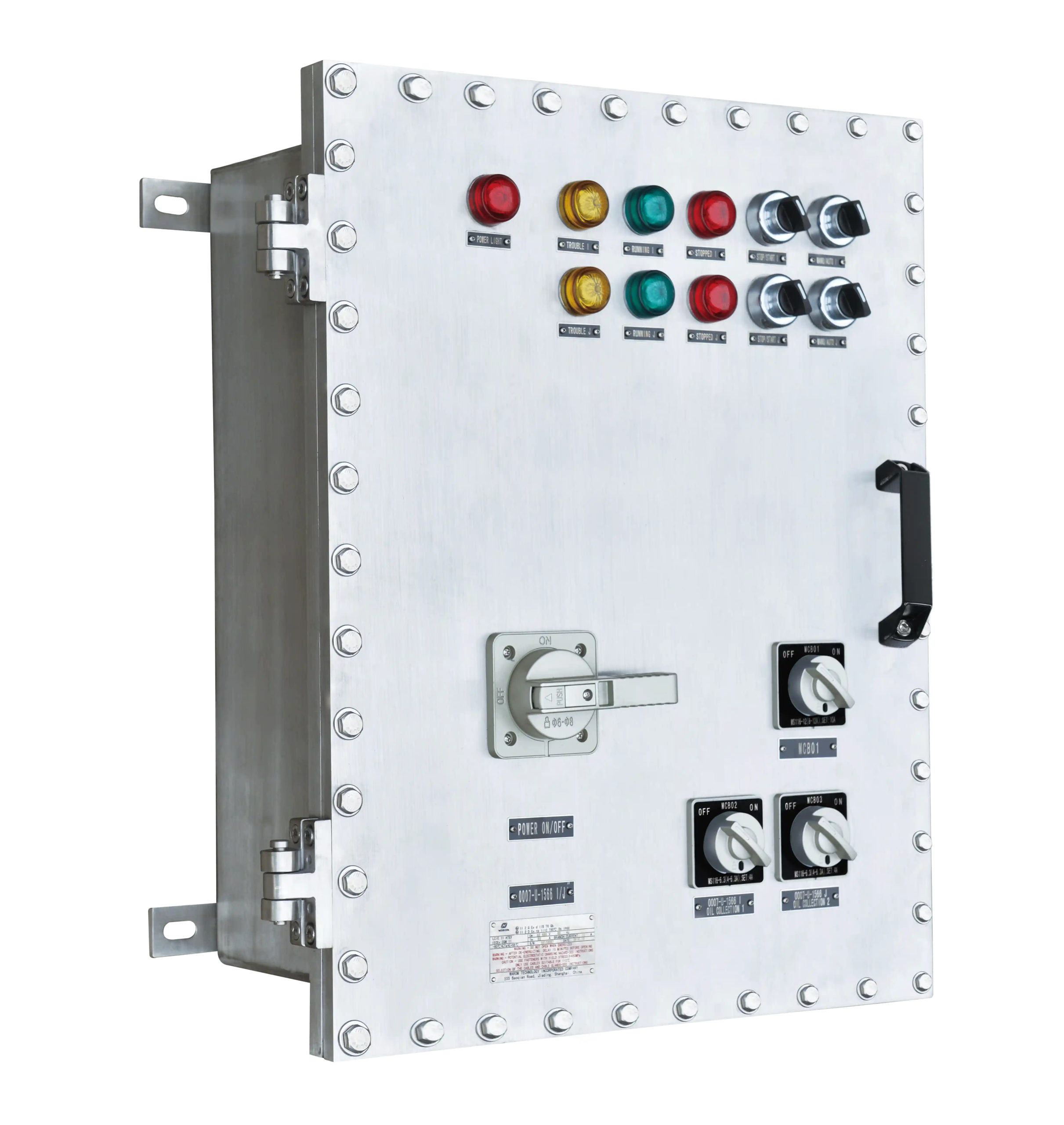
The HRMD92 Series distribution panels carry IP66 ratings specifically because Zone 1 applications demand that level of environmental sealing alongside the explosion protection. The two requirements are separate but both mandatory: the enclosure must contain an internal explosion and prevent external contaminants from entering.
In practice, achieving IP66 with cable glands requires proper installation. The compression seal must be torqued correctly, the cable diameter must fall within the gland’s specified range, and any unused entries must be plugged with certified blanking elements. A single improperly installed gland can compromise the entire enclosure’s IP rating.
When Conduit Systems Make More Sense Than Glands
Conduit provides something glands cannot: continuous mechanical protection along the entire cable run. In environments where cables face physical hazards—impact, abrasion, crushing, chemical exposure—conduit keeps the cable intact between enclosures.
Rigid conduit, typically galvanized steel or aluminum, handles the most demanding mechanical environments. The tradeoff is installation complexity: cutting, threading, bending, and fitting rigid conduit takes skilled labor and time. Every joint must be properly made, and the entire run must maintain electrical continuity for grounding purposes.
Flexible conduit addresses situations where rigid runs are impractical—connections to motors that vibrate, equipment that moves during operation, or routing around obstacles that would require excessive bends in rigid conduit. The flexibility comes with reduced mechanical protection compared to rigid conduit, so the application has to justify the tradeoff.
Sealing fittings are the critical component that makes conduit systems explosion-proof. Installed at specific intervals and at enclosure entries, these fittings contain a poured compound that blocks gas or vapor migration through the conduit interior. Without proper sealing fittings, a conduit run becomes a pathway for flammable atmospheres to travel between areas—potentially connecting a Zone 1 area to a non-hazardous space.
Drainage fittings handle condensation, which accumulates in any conduit system exposed to temperature cycling. Water pooling in conduit can damage cables, promote corrosion, and compromise sealing fittings over time.
The Tilenga project required extensive conduit runs because the cable routing crossed areas with significant mechanical hazards and the distances involved made individual gland entries impractical. The explosion-proof lighting and electrical systems we supplied had to integrate with conduit infrastructure that provided both protection and maintainability over the facility’s expected lifespan.
Does Installing Barrier Glands Require Special Training?
Yes, and this is where projects sometimes run into trouble. Barrier gland installation requires certified competent persons who understand the compound mixing ratios, curing times, and temperature requirements. The compound must fully encapsulate the conductors without voids or gaps, and it must cure completely before the circuit is energized.
Standard conduit fittings require skilled electricians but not the same specialized certification. The assembly is mechanical—threading, tightening, sealing—rather than chemical. An experienced electrician can install conduit fittings correctly without additional certification, though familiarity with explosion-proof requirements is still essential.
The training difference affects project planning. If barrier glands are specified but no certified installers are available on site, the project either delays or brings in specialized labor. Conduit systems avoid this bottleneck but introduce their own labor intensity.
Comparing the Two Approaches Across Real Project Factors
The choice between glands and conduit rarely comes down to a single factor. Cost, installation time, mechanical protection, and long-term maintenance all interact, and the right answer depends on the specific application.
| Factor | Cable Glands | Conduit Systems |
|---|---|---|
| Upfront cost | Lower per entry point | Higher for materials and labor |
| Installation speed | Faster for individual entries | Slower due to cutting, threading, sealing |
| Mechanical protection | At entry point only | Along entire cable run |
| Flexibility for cable types | High—various insert options | Moderate—cable must fit conduit ID |
| Maintenance access | Individual gland replacement | Section replacement may be needed |
For the General Paint project, the distribution boxes and junction boxes we provided used a combination of both methods. Main power feeds came through conduit for mechanical protection; instrument cables and control wiring used glands for faster installation and easier future modifications. The hybrid approach matched the actual site conditions rather than forcing a single solution everywhere.
Cost comparisons get complicated when you factor in labor rates, installation time, and future maintenance. Glands cost less per unit but require certified installers for barrier types. Conduit materials cost more, and the installation labor is substantial, but the mechanical protection may prevent cable damage that would otherwise require expensive repairs.
The risk assessment ultimately drives the decision. In a Zone 1 area with significant mechanical hazards, conduit’s protection justifies its cost. In a Zone 2 area with minimal physical risks, glands provide adequate protection at lower cost and faster installation.
What Actually Determines the Right Choice for a Specific Site
Environmental factors narrow the options before cost or preference enters the picture. Chemical exposure, temperature extremes, UV exposure, and vibration each eliminate certain materials and designs.
In corrosive chemical plant settings, material selection becomes the primary concern. Standard brass glands corrode; stainless steel or nickel-plated brass survives. Standard galvanized conduit degrades; PVC-coated steel or fiberglass-reinforced plastic (GRP) conduit handles the chemical exposure. The material choice affects both initial cost and expected service life.
Temperature extremes stress sealing compounds and gasket materials. A gland rated for -60°C to +90°C handles most industrial applications, but cryogenic or high-temperature processes may require specialized solutions. Conduit systems face similar constraints—thermal expansion and contraction can stress joints and compromise seals if not properly accounted for in the design.
Vibration environments favor robust mechanical connections. Conduit systems with proper supports resist vibration-induced loosening better than individual glands, though anti-vibration gland designs exist for dynamic applications. The vibration frequency and amplitude matter; low-frequency, high-amplitude vibration from reciprocating equipment differs from high-frequency vibration from rotating machinery.
Regulatory compliance is non-negotiable. ATEX certification is mandatory for European installations; IECEx provides global acceptance. North American projects may require NEC compliance in addition to or instead of international certifications. The certification requirements must be verified before any equipment is specified, and the documentation must be maintained throughout the installation.
The Fushilai Pharmaceutical project required careful material selection because pharmaceutical facilities often involve both explosion hazards and stringent cleanliness requirements. The distribution boxes we provided had to meet explosion-proof standards while also being compatible with washdown procedures and chemical cleaning agents used in pharmaceutical manufacturing.
How Do Material Choices Affect Long-Term Performance in Corrosive Environments?
Material degradation in corrosive environments follows predictable patterns, but the timeline varies dramatically based on the specific chemicals involved. Chlorine compounds attack brass aggressively; stainless steel resists but is not immune. Sulfuric acid environments may require exotic alloys or non-metallic solutions.
For glands, the body material, sealing elements, and any internal components all need to resist the expected chemical exposure. A stainless steel gland body with a standard nitrile seal fails if the seal degrades—the body’s corrosion resistance is irrelevant once the seal leaks.
Conduit material selection follows similar logic. PVC-coated galvanized steel handles many chemical environments, but the coating must remain intact. Any damage to the coating exposes the underlying steel to corrosion. GRP conduit avoids this issue but has lower mechanical strength and different installation requirements.
Long-term durability also depends on maintenance practices. Regular inspections catch early corrosion before it compromises the explosion protection. Replacement schedules based on expected material life prevent failures. The initial material selection should account for the intended inspection and replacement intervals.
Installation and Maintenance Practices That Actually Matter
Correct installation is the difference between a system that performs for decades and one that fails its first inspection. The equipment can be perfectly specified, but improper installation negates the certification.
For cable glands, torque settings are critical. Under-torqued glands do not achieve proper compression; over-torqued glands can damage the cable sheath or the gland itself. Manufacturer specifications provide the correct values, and calibrated torque wrenches ensure compliance.
Barrier gland compound application requires attention to temperature and curing time. The compound must be mixed correctly, poured without introducing air bubbles, and allowed to cure completely before the cable is energized. Rushing this process—a common temptation when project schedules slip—creates gas pathways that defeat the barrier function.
Conduit systems require proper grounding and bonding throughout the run. Electrical continuity must be verified, and any paint or coatings that might interfere with grounding must be addressed. Sealing fittings must be installed at the correct locations—typically within 18 inches of enclosure entries and at intervals specified by the applicable code.
Routine maintenance includes visual inspections for damage, corrosion, or loosening. Glands should be checked for proper compression; conduit joints should be checked for integrity. Any signs of compound degradation in barrier glands or sealing fittings indicate the need for replacement.
The Tilenga project’s zero safety incident record during installation reflected rigorous adherence to these practices. Every gland was torqued to specification, every sealing fitting was properly filled and cured, and every conduit run was verified for continuity before energization.
Frequently Asked Questions
How much faster are cable glands to install compared to conduit systems?
For individual cable entries, glands typically install in minutes once the cable is prepared—stripping the sheath, inserting through the gland, tightening the compression, and (for barrier types) filling and curing the compound. Conduit runs require measuring, cutting, threading, assembling fittings, pulling cable, and installing sealing fittings. A single conduit run to a distribution box might take several hours where multiple gland entries would take under an hour total. The difference compounds across a project with dozens or hundreds of cable entries.
Do extreme temperatures or vibration change which cable entry method works better?
Temperature extremes affect sealing compounds in both barrier glands and conduit sealing fittings. Verify the rated temperature range covers your actual operating conditions with margin for excursions. Vibration generally favors conduit systems because the rigid structure resists loosening better than individual glands, though anti-vibration gland designs exist for applications where conduit is impractical. High-vibration environments like compressor stations often use conduit for main runs with flexible sections near the vibrating equipment.
Can you use both glands and conduit on the same distribution box?
Yes, and this hybrid approach is common in practice. Conduit handles main power feeds where mechanical protection matters most; glands handle instrument cables and control wiring where flexibility and faster installation are priorities. The distribution box needs appropriate entries for both—threaded conduit hubs and gland entry holes—which requires specifying the configuration during procurement. Mixing methods within a single project is normal; mixing methods on a single cable run is not.
What certifications matter for international explosion-proof projects?
ATEX is mandatory for European Union installations and widely recognized elsewhere. IECEx provides the broadest international acceptance and is often required for projects outside Europe. North American projects typically require equipment listed to NEC standards, which may involve UL or FM certifications. Some countries accept IECEx directly; others require local certification based on IECEx test reports. Verify the specific requirements for your installation location before specifying equipment—retrofitting non-compliant equipment is expensive and time-consuming.
What is the most common installation mistake with barrier glands?
Incomplete compound curing. Installers under schedule pressure sometimes energize circuits before the barrier compound has fully cured, or they pour compound at temperatures outside the specified range, resulting in incomplete curing. Either situation leaves gas pathways through the gland that defeat its purpose. The compound must reach full cure—verified by time and temperature, not by appearance—before the circuit goes live. If you need to discuss specific compound requirements or curing verification methods for your project conditions, contact our technical team at +86 21 39977076.
If you’re interested, you may want to read the following articles:
Warom Technology “International explosion-proof technology Vietnam special Forum” was successfully held
The New Factory of WAROM MENA
Warom wishes you all a Happy Labor Day!
Choosing Temporary Construction Lighting: An Ultimate Safety Guide
With over a decade of experience, he is a seasoned Explosion-Proof Electrical Engineer specializing in the design and manufacture of safety and explosion-proof products. He possesses in-depth expertise across key areas including explosion-proof systems, nuclear power lighting, marine safety, fire protection, and intelligent control systems. At Warom Technology Incorporated Company, he holds dual leadership roles as Deputy Chief Engineer for International Business and Head of the International R&D Department, where he oversees R&D initiatives and ensures the precise delivery of design documentation for international projects. Committed to advancing global industrial safety, he focuses on translating complex technologies into practical solutions, helping clients implement safer, smarter, and more reliable control systems worldwide.
Qi Lingyi