

Most explosion proof lighting distribution boxes I review on project schedules are treated as a minor package item. The more useful starting point is the installed lighting circuit inventory: number of outgoing ways, cable diameters, gland type, ambient temperature, and whether the enclosure sits in Zone 1 or Zone 2. When the enclosure is chosen before those details are fixed, the usual result is either a field modification or a certificate condition that no longer matches the installed method. I use that order to keep the distribution box certified and the lighting network easy to maintain without rework.
Hazardous Area Classification Sets the Minimum Explosion Proof Lighting Distribution Box Requirements
Lighting distribution boxes in hazardous areas are not always flameproof enclosures. Many lighting panels are built as increased safety Ex e enclosures with flameproof switching or circuit breaker compartments inside. That compound design keeps the enclosure accessible while containing the arcing components in an Ex d chamber. The BXM(D)8050 is one family we use for this type of panel because it combines an Ex d chamber with an Ex e enclosure and carries an IP66 rating. The classification still has to be checked first.
Zone 1 gas areas with IIC gases demand a stricter protection concept than Zone 2, even when the connected loads are identical. For dust, Zone 21 and Zone 22 add surface temperature and dust group checks that a gas only certificate may not cover. I ask the project team for the area classification drawing and the gas group before any enclosure material or circuit arrangement is discussed.
| Area | Typical protection | What I verify |
|---|---|---|
| Zone 1 gas | Ex d or compound Ex d and Ex e | Gas group IIC, temperature class, certified entries |
| Zone 2 gas | Ex e or Ex nA | Zone 2 certificate, ambient range, gland rating |
| Zone 21 dust | Ex tb IIIC | Dust layer, IP66, surface temperature |
| Zone 22 dust | Ex tc IIIB or IIIC | Fiber accumulation, cleaning access, overtemperature |
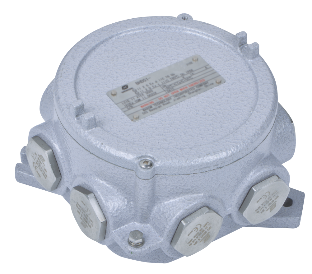
Explosion Proof Lighting Distribution Box Enclosure and Cable Entry Design Must Match Each Lighting Circuit
An explosion proof lighting distribution box fails at the interface before it fails at the enclosure. Cable entry holes are machined to suit the glands and cables specified at order time. If the contractor later brings armored cable instead of unarmored cable, or changes from metric to NPT threads, the holes and glands no longer fit without workshop modification. On one overseas chemical lighting package, the initial design used gland plates for 12.5 to 20.5 mm cable outer diameters. The final lighting loop schedule moved to 6 mm² armored cores with larger overall diameters, so the entry plate had to be redrawn before fabrication. The change was caught early and avoided non-certified holes in the field.
Cable entry choices affect the enclosure drawing and the installers’ work in the field. <Explosion Proof Distribution Box: Glands vs Conduit for Safety> covers the practical trade-offs between direct cable gland entry and conduit systems, including where each method creates cost or inspection problems.
Enclosure material is the other decision that is fixed too early. The options below cover most lighting distribution panels we review.
| Material | Typical application | What to check |
|---|---|---|
| GRP | Chemical and coastal lighting panels | IP66, corrosion resistance, lower weight |
| Copper-free aluminium alloy | Oil, gas, and process units | IP66, wide ambient range, mechanical strength |
| Stainless steel | Marine and saltwater exposure | Corrosion resistance, higher machining cost |
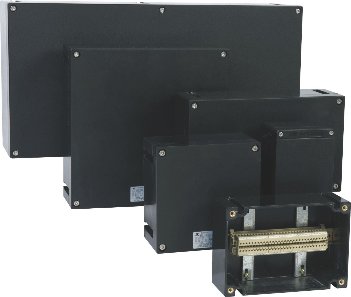
Terminal Ratings and Circuit Configuration Set the Real Explosion Proof Lighting Distribution Box Capacity
Terminal ratings are the least visible constraint inside a distribution box. A 6 mm² terminal may be marked for 41 A in a BHD91 junction box, but the practical circuit load should be lower when the box sits in an ambient above 40°C or when several outgoing lighting circuits share one enclosure. In an Ex e terminal box such as the BXJ8050, the current ratings move with the conductor cross section: 20 A at 2.5 mm², 28 A at 4 mm², 35 A at 6 mm², 45 A at 10 mm², 60 A at 16 mm², and 100 A at 35 mm². Those figures assume the terminal row is not packed and the certificate conditions are met. That is why I ask for the maximum protective device setting with the circuit schedule, not just the connected wattage.
LED lighting loads can be small enough that the panel is mechanically full long before it is electrically loaded. The difficulty shifts from current density to cable entry space and terminal access. For lighting tower and process area circuits, I prefer to keep the number of outgoing ways below the certified terminal count and to reserve spare ways for commissioning changes. On the General Paint chemical plant in Mexico, the distribution equipment had to handle flammable gas and dust risks, so the outgoing circuit arrangement was designed around the existing cabling conditions and the need to isolate sections quickly during maintenance. A panel with no spare entry capacity leaves a maintenance team with difficult choices.
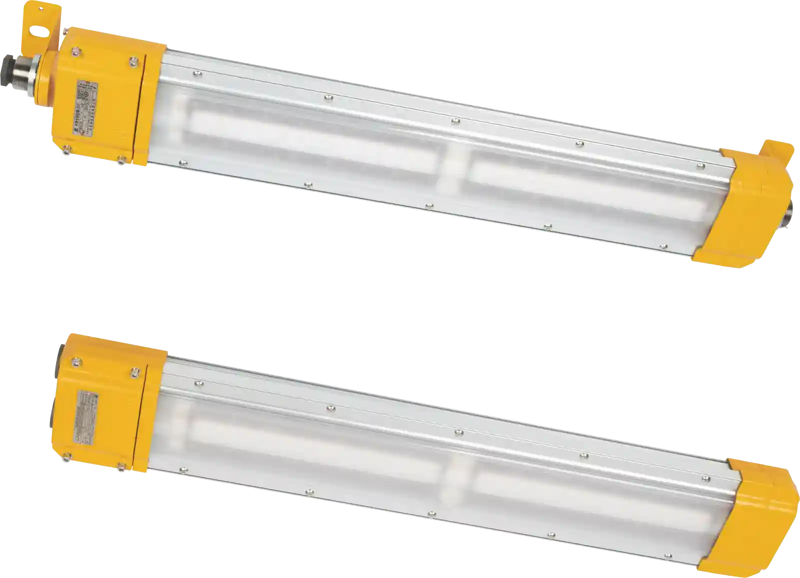
At this point I usually ask the project engineer to confirm the full outgoing circuit list before freezing the bill of materials. If the list includes mixed Ex d breakers and Ex e terminals in one enclosure, the physical arrangement needs a layout check. Send the circuit schedule to gm*@***om.com and we can confirm the enclosure drawing against the certificate.
The panel protects the distribution, but the connected fitting is where the circuit risks start. <Explosion Proof LED Lights: Guide to Hazardous Area Safety> covers the light fitting ratings and installation details that need to be aligned with the distribution panel’s outgoing protection.
Certificate and Nameplate Data Must Match the Project Specification
A distribution box is only explosion proof when the certificate, nameplate, and installation practice stay aligned. I look at two sections of the certificate first: the standards listed and any special conditions marked with an X. An Ex e lighting distribution box should reference IEC 60079-0 and IEC 60079-7, with the enclosure type, gas group, temperature class, ambient range, and IP rating shown on the nameplate. If the certificate carries X conditions, those conditions are part of the approval. A common one is a restriction on cable entries or a required minimum cable length inside the enclosure. A field change that violates an X condition can invalidate the certification even if the enclosure itself is unchanged.
For lighting circuits, the cable gland certificate matters just as much as the panel certificate. DQM-II and DQM-III Ex d glands are certified to IEC 60079-0, IEC 60079-1, and IEC 60079-7 and rated IP66, but the installer still has to match the gland to the cable outer diameter and the enclosure entry thread. Before factory acceptance, I compare the nameplate against four data points: gas group, temperature class, ambient temperature, and cable entry thread form.
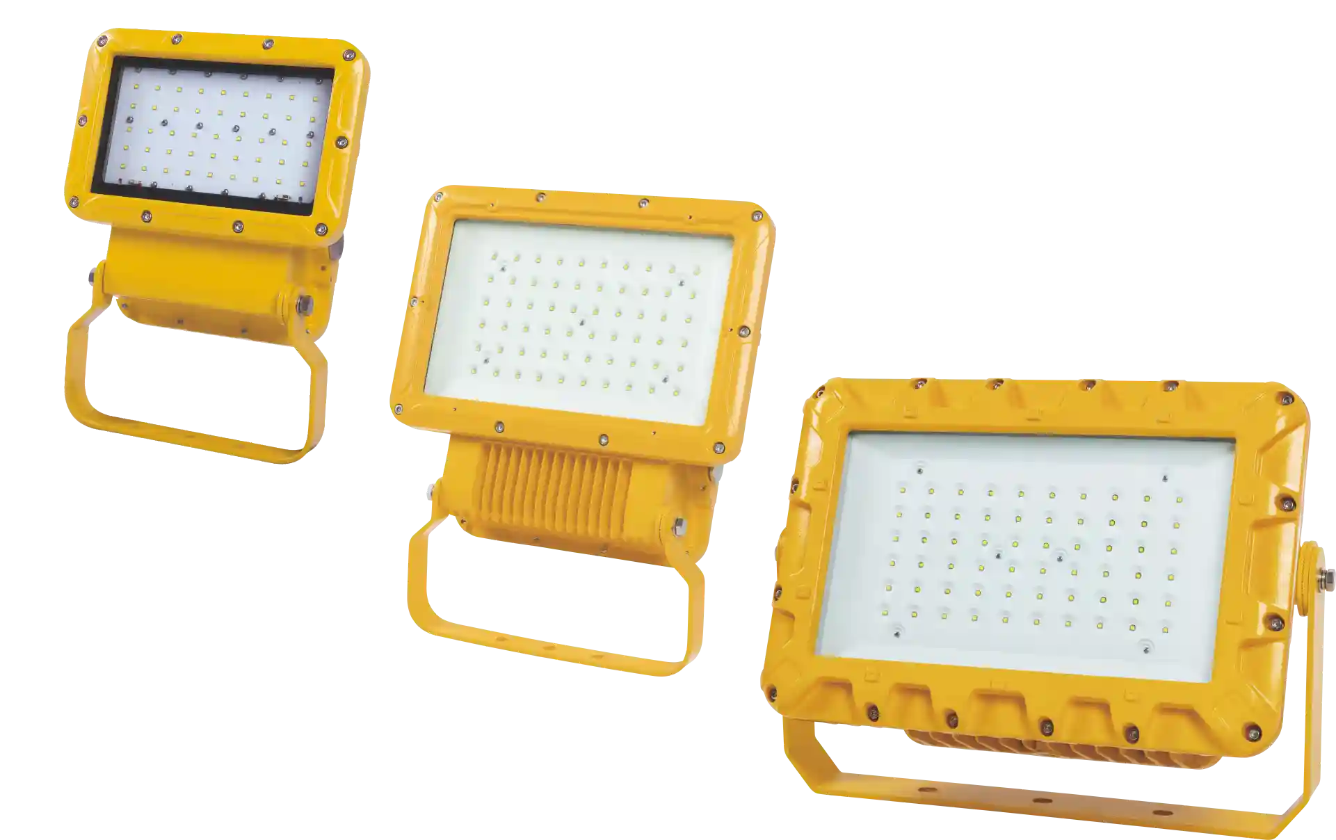
Sending the Circuit Schedule and Cable List Early Prevents Field Rework
Most enclosure rework comes from a missing input, not a wrong product. When a lighting distribution box is ordered with spare holes, standard glands, and a fixed terminal layout, site changes become expensive. If the project has long cable runs, mixed armored and unarmored circuits, or metric to NPT conversion, I would rather review the panel before the enclosure drawing is approved. Send the lighting circuit schedule, cable outer diameters, gland preference, and area classification to gm*@***om.com. For urgent drawing reviews, call +86 21 39977076 or +86 21 39972657 and ask for the explosion proof distribution group. The aim is a panel that fits the installation exactly, not one that has to be adapted on site.
Procurement Engineers Ask These Questions About Explosion Proof Lighting Distribution Boxes
Can one lighting distribution box serve both Zone 1 and Zone 2 circuits?
No. Even if the enclosure certificate covers both zones, the conditioned use has to be shown for each zone. A Zone 1 circuit with IIC gas and a T4 temperature class may require Ex d switching, while a Zone 2 circuit may use Ex e terminals and a different cable entry arrangement. If both are mixed in one panel, the certificate conditions, terminal segregation, and gland ratings must be reviewed against the area classification drawing. In practice, I treat them as separate sections unless the panel was designed and certified that way.
Is GRP strong enough for a process area, or should I always specify aluminium?
The assumption that GRP is weak is inaccurate. GRP is chosen for corrosion resistance and lower weight; it is not a substitute where mechanical impact is the main concern. A chemical loading bay with salt spray and regular washdown is often better served by GRP with IP66. A gas compression skid with pipe wrenches and valve access nearby may justify aluminium. The deciding factors are impact risk, chemical exposure, sunlight, and whether the mounting surface moves.
Does an IP66 rating automatically make a lighting distribution box explosion proof?
It depends on the protection concept. IP66 addresses solid and liquid ingress. Explosion protection is determined by the Ex marking for Ex d, Ex e, or a compound design, not by the IP code alone. An IP66 weatherproof panel used in a hazardous area is still a weatherproof panel unless it carries the appropriate ATEX or IECEx marking. The correct enclosure often has both IP66 and an Ex certificate, but the two ratings answer different failure modes.
What is the most common late change in a lighting distribution box order?
In projects we have supplied, the most common late change is a cable entry modification after the enclosure drawing has been approved. The original drawing usually assumes standard metric entries and a fixed cable diameter. When the cable schedule changes, the hole pattern, gland thread, and sometimes the terminal orientation change with it. If the site waits until installation to catch this, the panel may need rework or field drilling that invalidates the certificate. Share the gland and cable schedule with gm*@***om.com before the drawing is approved, and we can confirm whether the entries can stay as designed.
If you’re interested, check out these related articles:
Warom Invites You to 2025 China International Maritime Technology & Academic Conference and Exhibition
Guide to Hazardous Location Lighting: Standards and Selection
Warom at Vietnam ETE 2024
WAROM With our partner in OGU
Explosion-Proof DOL Motor Starters: Essential Specifications and Selection
With over a decade of experience, he is a seasoned Explosion-Proof Electrical Engineer specializing in the design and manufacture of safety and explosion-proof products. He possesses in-depth expertise across key areas including explosion-proof systems, nuclear power lighting, marine safety, fire protection, and intelligent control systems. At Warom Technology Incorporated Company, he holds dual leadership roles as Deputy Chief Engineer for International Business and Head of the International R&D Department, where he oversees R&D initiatives and ensures the precise delivery of design documentation for international projects. Committed to advancing global industrial safety, he focuses on translating complex technologies into practical solutions, helping clients implement safer, smarter, and more reliable control systems worldwide.

Qi Lingyi