

Explosion proof temperature transmitters fail in hazardous process areas less often because of sensor drift than because the specification did not match the installation. We have seen loops that measured accurately on the bench and then drifted, shorted, or lost certification traceability after installation where the enclosure type, temperature class, or cable entry did not reflect the actual process conditions. Before comparing models, the first decision is not which transmitter is best. It is which protection concept and process connection the loop actually requires. This article works through those variables and the documentation to collect before shipment.
Why Do Explosion Proof Temperature Transmitters Fail in Process Areas?
The most common failure I see is not the sensing element. It is the boundary between the process, the housing, and the field wiring. A transmitter that passes a bench calibration can still fail at startup because a cable gland was sized for the wrong cable outer diameter, or because an unused entry was fitted with a plug that did not maintain the enclosure rating.
Temperature class is the second common problem. A transmitter may carry an Ex d IIC T6 certificate, but if the process runs near the maximum ambient temperature for that class, the electronics run hot. The enclosure surface temperature can rise beyond what the installation permits, especially in direct sun or on a hot pipe. When the ambient temperature is not stated on the data sheet, the temperature class claim is incomplete. I have watched startups where a device rated T4 was installed on a process line that reached 70 degrees Celsius without any correction for solar load. The transmitter still worked, but the certified protection story no longer held.
Moisture ingress produces a different failure. It starts as a small offset in the loop reading and ends as corrosion on the terminal block. In process areas, the enclosure rating and the gland installation matter as much as the flame path. IP66 is common, but that rating assumes correct installation with compatible cable, correct gland torque, and sealed unused entries.
Which Protection Concept Is Right for a Temperature Transmitter?
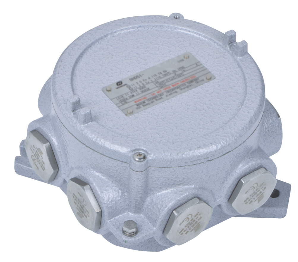
Explosion proof temperature transmitters can be built around several protection concepts, and the right choice depends on the zone, the wiring system, and whether the loop will be serviced live. In practice, most projects settle between Ex d flameproof and Ex i intrinsic safety.
Ex d puts the transmitter electronics and terminals inside a flameproof enclosure. An internal ignition is contained and cooled before it can reach the outside atmosphere. This is mechanically simple and works with standard field wiring, but the enclosure is heavier and field adjustment normally requires removing power. Ex i limits energy in the loop through a certified barrier or isolator. The transmitter and sensor circuit cannot release enough energy to ignite the gas, which can allow safe live maintenance in higher zones when the barrier parameters align. Ex nA or Ex ec appears in Zone 2 installations where the cost of flameproof or intrinsic safety is harder to justify.
| Consideration | Ex d Flameproof | Ex i Intrinsic Safety | Ex nA / Ex ec |
|---|---|---|---|
| Typical zone use | Zone 1 or Zone 2 | Zone 0, Zone 1 or Zone 2 | Zone 2 only |
| Live field adjustment | Power removal normally required | Possible if barrier parameters allow | Limited |
| Additional equipment | None for the loop | Certified barrier or isolator required | None |
| Enclosure impact | Heavier and larger | Lighter transmitter body | Lighter transmitter body |
If your facility mixes NEC Division ratings and IEC Zone markings, the same approval logic applies to transmitters as to other field devices. <NEMA 7 vs ATEX Certified Explosion Proof Control Stations> covers how those two certification paths compare and what changes for enclosure selection.
The decision becomes easier when you ask one question: will this loop be opened while the area is live? If yes, work through an Ex i design with a certified barrier and confirm the entity parameters. If no, an Ex d transmitter may fit the project with fewer interface components.
What Do Sensor Type, Output and Accuracy Mean for the Control Loop?
Most process temperature transmitters use a Pt100 RTD or a thermocouple. A Pt100 with a 4 to 20 mA HART output is a solid default for reactor jackets, separators, and storage tanks because the signal is stable, the wiring is familiar, and the transmitter can push diagnostic data back to the control system. Thermocouples suit wider temperature ranges, but cold junction compensation becomes a real error source if the terminal block temperature changes after commissioning.
Accuracy is only part of the loop. A transmitter with 0.1 percent accuracy will not fix a poorly selected thermowell, a sensor that is not fully immersed, or cable runs that pick up noise near drives. For control, I prefer to state the expected process span, then ask for the accuracy figure across that span at the operating ambient temperature. A number quoted only at room temperature tells you less than it appears to.
The output signal should match the DCS and the maintenance plan. HART gives access to diagnostics without pulling the transmitter. A second sensor channel helps when the process has trips based on temperature or when online drift checks matter. If the loop is safety related, confirm whether the transmitter carries a SIL rating, and ask for the failure data in the certificate package rather than accepting a logo on the data sheet.
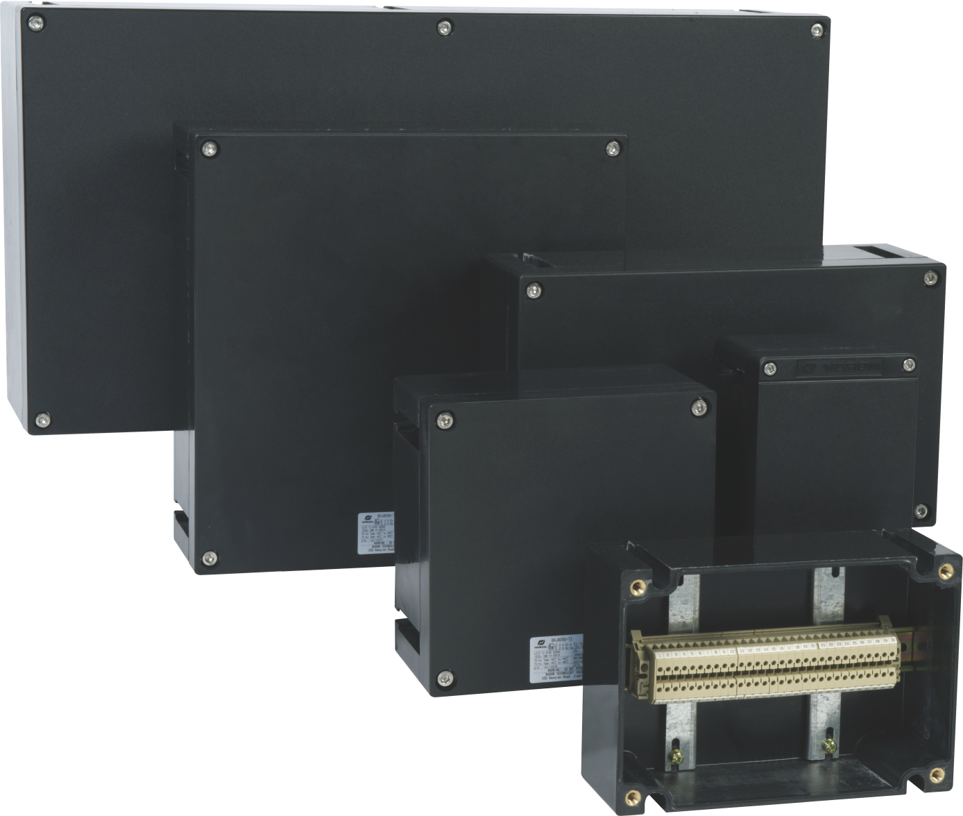
If your loop includes a thermocouple in Zone 1 and you are mixing Ex i field devices with Ex d junction boxes, confirm the barrier parameters and cable routing before freezing the BOM. Email gm*@***om.com with the loop drawing and we will check the configuration.
Which Installation Details Keep Temperature Transmitters Working?
Cable entry is where many explosion proof temperature transmitter installations go wrong. The gland must match the cable outer diameter, the cable type, and the protection concept. A flameproof enclosure requires a gland certified for Ex d with a flame path suited to the cable. An intrinsically safe loop still needs mechanical sealing for moisture and dust, but the energy limitation comes from the barrier.
Install the transmitter so water cannot collect around the entry. Bottom entries are common, but they need glands with proper sealing and no upward strain on the cable. In wet process areas, a drain plug can help, but only if the drain is positioned so it cannot be mistaken for an unused entry. I have seen water enter through a temporary blanking plug left in place after construction, and the resulting faults were intermittent and difficult to trace.
Process connection and thermowell selection matter before the transmitter is considered. The thermowell must reach the point in the process stream where the temperature measurement is representative, and it must resist erosion or vibration. In high vibration areas, a transmitter mounted directly on the thermowell may fail prematurely; a remote mount or a short extension with a braced sensor can reduce that failure mode.
How Do You Select Explosion Proof Temperature Transmitters Without Guesswork?
The specification becomes manageable when you work in sequence. Confirm the hazardous area zone, the gas group, and the temperature class from the area classification drawing. Then confirm the process temperature span, the sensor type, the process connection, and the output expected by the control system. After that, specify the enclosure ingress protection, the cable entry type, and the certification package. The transmitter model becomes the result of those decisions, not the starting point.
Too many transmitter selections begin with a product list and then try to make the site conditions fit. That reverses the process and leaves gaps that surface during FAT or startup. For EPC packages with multiple field devices on one project specification, the electrical package needs more than transmitter data sheets. <Specifying Explosion-Proof Electricals for EPC Projects: Safety & Compliance> covers how documentation, certification alignment, and installation details are handled before the BOM is frozen.
If your process area includes aggressive chemicals, frequent CIP or washdown, or combined gas and dust hazards, the enclosure material and cable entry selection need a second look. We normally ask for the area classification drawing, the process data sheet, and the loop list before recommending a configuration. Send those documents to gm*@***om.com or call +86 21 39977076 +86 21 39972657. We will cross-check the transmitter protection concept against the gas group and temperature class and confirm what documentation is available before shipment.
What Do Buyers Ask About Explosion Proof Temperature Transmitters?
What is the difference between explosion proof and intrinsically safe temperature transmitters?
An explosion proof transmitter contains an explosion and prevents flame from reaching the outside atmosphere. An intrinsically safe transmitter is designed with a low energy circuit and relies on a certified barrier or isolator to keep energy below ignition limits. For a temperature transmitter, both approaches can be valid in Zone 1. The practical difference is how you wire and service the loop. Explosion proof is self contained but heavier and normally requires de energizing before opening. Intrinsic safety adds a barrier and requires entity parameter matching, but it can allow live maintenance in hazardous areas when the installation follows the certificate.
How do I confirm the transmitter is certified for Zone 1?
Do not stop at a statement on the bill of materials. Find the certificate number and the marking on the nameplate. The marking should state the protection concept, gas group, temperature class, and certificate issuer. Cross-check the certificate against the project standard, whether that is ATEX, IECEx, or a local requirement. If the site also has dust hazards, confirm that the certificate covers the dust zone. If the nameplate and the data sheet do not match, that is a problem to resolve before shipment. The certificate matters more than the word explosion proof in a catalog.
Do explosion proof temperature transmitters require special cable glands?
In most cases, yes. For an Ex d transmitter in Zone 1, the gland is part of the explosion protection system and must be certified for the cable type and cable outer diameter. An ordinary industrial gland may seal against water but does not form the correct flame path. For an Ex i loop, the gland still needs to maintain the enclosure IP rating and provide reliable mechanical retention. When the cable type changes late in a project, recheck the gland compatibility. That is one of the most frequent last minute changes we see.
What information should I include in an RFQ for an explosion proof temperature transmitter?
Start with the area classification drawing, the gas group, the temperature class, and the zone. Then add the process temperature range, sensor type, process connection size and material, thermowell details, output signal, and enclosure protection. Include the ambient temperature range and any site conditions such as vibration, washdown, or coastal salt exposure. If you know the cable outer diameter and gland entry thread, include that too. A complete RFQ reduces the back and forth and produces quotes that can be compared directly. Send the data sheet and zone drawing to gm*@***om.com and we will confirm compliance documentation availability.
If you’re interested, check out these related articles:
Happy National Day
Warom won the title of Excellent Purveyor
The 137th Canton Fair is Underway
Day 2 of Australian Energy Producers Conference & Exhibition 2025
With over a decade of experience, he is a seasoned Explosion-Proof Electrical Engineer specializing in the design and manufacture of safety and explosion-proof products. He possesses in-depth expertise across key areas including explosion-proof systems, nuclear power lighting, marine safety, fire protection, and intelligent control systems. At Warom Technology Incorporated Company, he holds dual leadership roles as Deputy Chief Engineer for International Business and Head of the International R&D Department, where he oversees R&D initiatives and ensures the precise delivery of design documentation for international projects. Committed to advancing global industrial safety, he focuses on translating complex technologies into practical solutions, helping clients implement safer, smarter, and more reliable control systems worldwide.

Qi Lingyi