

Selecting explosion proof level sensors for hazardous area storage tanks comes down to three linked decisions: the classification of the space the instrument sees, the protection method the measurement technology allows, and the evidence you can verify before release. The common failure is treating one of these as a formality. An instrument marked for Zone 1 is not automatically right for a tank whose vapour space is Zone 0, and a certificate number quoted in a supplier email is not the same as an applicable certificate for the configured device. This guide follows the order a specification normally takes: classification, protection, technology, verification, and handover.
What Makes a Level Sensor Suitable for a Hazardous Area Tank?
The tank sets the requirement before the instrument does. Inside a storage tank, the space above the liquid can hold a flammable atmosphere, and the area classification drawing for the unit normally states how that space is classified. Zone 0 covers a space in which an explosive gas atmosphere is present continuously, for long periods, or frequently. Zone 1 covers a space in which it is likely to occur during normal operation, and Zone 2 covers a space in which it is unlikely and, if it occurs, persists only briefly [1].
Equipment protection level states the same requirement in a form that travels with the instrument. Ga is the level associated with Zone 0, Gb with Zone 1, and Gc with Zone 2 [2]. A sensor quoting Gb is therefore a legitimate instrument and still the wrong one for a Zone 0 vapour space. A split design is the usual answer, with a passive probe certified for the tank interior and the transmitter head certified for the roof area.
| Space being classified | Minimum EPL | Protection concepts commonly used | What it changes for a level sensor |
|---|---|---|---|
| Zone 0 inside the tank | Ga | Ex ia, Ex ma, or a certified combination | The wetted probe and any circuit inside the tank must be rated for continuous exposure |
| Zone 1 inside the tank or at the roof | Gb | Ex d, Ex e, Ex ib, Ex px | Either a flameproof housing or an intrinsically safe loop is acceptable |
| Zone 2 inside the tank or at the roof | Gc | Ex ec, Ex ic, Ex n | Fault tolerance is reduced, but gas group and temperature class still apply |
| Split design, probe in Zone 0 and head in Zone 1 | Ga for the probe, Gb for the head | Ex ia probe with a separate transmitter | Each part needs its own certification and a compatible interface |
Two further values complete the classification. The gas group describes the vapour the equipment must tolerate, with IIA, IIB, and IIC ordered by the stringency of the gap and energy limits, and IIC covering hydrogen and acetylene. The temperature class fixes the maximum surface temperature the equipment may reach, from T1 at 450 °C down to T6 at 85 °C [2]. Neither value can be inferred from the product name on the tank; both come from the process data and the area classification study.
Explosion proof is a working term rather than a single certification. It covers several protection concepts that remove ignition risk by different mechanisms, and the marking tells you which one you actually have. Buyers who read the term as a uniform quality label end up comparing instruments that are not comparable.
Buyers often meet the term before they meet the marking, and the two are not interchangeable. <Explosion Proof Definition: Essential 2025 Safety Facts> covers the definition of explosion proof equipment and the safety facts behind the marking.
Which Protection Method Fits Your Sensor and Loop?
Intrinsic safety limits the electrical energy that can enter the hazardous area, so that neither a spark nor a hot surface can ignite the atmosphere under the fault conditions defined in the standard [3]. The instrument is separated from the safe area by a barrier or a galvanic isolator, and the loop is checked against entity parameters: the barrier output voltage, current, and power against the instrument input values, and the cable capacitance and inductance against the permitted cable values.
Flameproof protection takes the opposite approach. The enclosure withstands an internal explosion and cools the escaping gases through a defined flame path, so the surrounding atmosphere is not ignited [4]. Inside the enclosure, ordinary energy levels are permitted. The method depends on joint dimensions and on certified cable entry devices, which is why a flameproof instrument is only as good as its entries and its maintenance practice.
| Protection method | How it controls ignition risk | Typical level sensor use | Constraint to confirm |
|---|---|---|---|
| Ex ia intrinsic safety | Limits energy entering the loop | Radar, capacitance, and pressure transmitters in Zone 0 or Zone 1 | Entity parameters and cable values must be calculated for the whole loop |
| Ex d flameproof | Contains an internal explosion and quenches the flame path | Float switches and transmitters with higher-power electronics in Zone 1 | Certified entry devices and flame path condition, and not accepted in Zone 0 |
| Ex e increased safety | Prevents sparking and hot spots through design clearances | Terminal and junction enclosures on the instrument circuit | Applies to connection and terminal equipment, not to a sensing element alone |
| Ex m encapsulation | Seals the circuit in a compound | Compact probes and switch modules | Repair is normally replacement |
| Ex t dust protection by enclosure | Keeps dust out and limits surface temperature | Instruments in dust zones around solids handling | Dust group and maximum surface temperature must be marked |
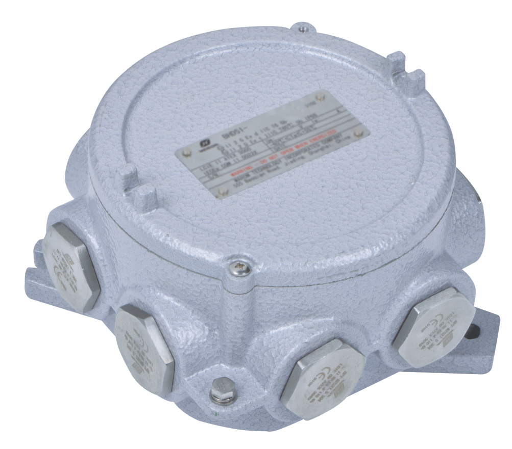
Whichever method is used, the cable entry is part of the certification. A flameproof instrument fitted with an uncertified gland loses its protection, and an intrinsically safe circuit still needs screened cable, correct gland selection, and a clean earth reference. Installation practice then follows the protection concept, including the selection and erection requirements for cable, entry, and earthing [5]. Instrument loops are normally terminated in an enclosure that carries its own marking, and that enclosure enters the inspection scope along with the sensor.
Where the instrument contributes to overfill protection, the loop also has a functional safety dimension. IEC 61508 sets out the framework for safety-related systems and the meaning of a SIL claim [6]. A SIL-capable sensor is a component claim; the achieved level belongs to the complete loop, including the logic solver and the final element, and to the proof-test interval the site can sustain in practice.
Comparing Level Measurement Technologies for Storage Tanks
The measurement technology decides which protection concepts are available and what the maintenance burden looks like over the life of the tank. There is no single best technology. Each one fails under conditions you can identify in advance.
| Technology | Protection commonly applied | Where it works well | What to verify before selecting |
|---|---|---|---|
| Guided wave radar | Ex ia or Ex d | Clean liquids, level and interface from one instrument | Dielectric contrast between the two liquids, and probe coating in viscous service |
| Non-contact radar | Ex ia or Ex d | Tanks with no room for a probe and corrosive products | Low-dielectric media, foam, and vapour can weaken the return echo |
| Capacitance | Ex ia | Simple level and pump control duties | Product coating on the probe changes the reading and forces recalibration |
| Hydrostatic pressure transmitter | Ex ia or Ex d | Pressurised and open tanks with a stable density | Density changes shift the reading, so compensation has to be defined |
| Magnetic float switch | Ex d or Ex ia contacts | Discrete high or low alarms and pump duty | Sticking, mechanical wear, and build-up on the float |
| Ultrasonic | Ex ia or Ex d | Non-contact measurement in open tanks | Vapour, temperature layers, and foam affect the speed of sound |
Dielectric constant is the value that decides most radar selections and the one most often missing from an enquiry. A product with a low dielectric constant returns a weak echo, and the same instrument that performs well on a wet hydrocarbon can lose the reflection entirely in a dry light product. Where two liquids are present, an interface measurement needs a meaningful dielectric difference between them; if an emulsion band forms, the reading sits somewhere inside that band and the accuracy figure in the datasheet no longer describes your tank.
Two practical rules follow. First, a continuous transmitter and a discrete overfill switch should be separate instruments, so that one failure does not remove both the routine reading and the alarm. Second, moving parts belong where a stuck float can be found quickly, which usually means a tank with regular operator access rather than a remote tank watched from a control room.
How Temperature Class and Process Conditions Change the Selection
Temperature class is not a ranking. It states the maximum surface temperature the equipment may reach under its rated conditions, and each class corresponds to a fixed value [2].
| Temperature class | Maximum surface temperature |
|---|---|
| T1 | 450 °C |
| T2 | 300 °C |
| T3 | 200 °C |
| T4 | 135 °C |
| T5 | 100 °C |
| T6 | 85 °C |
Choosing a class means comparing that value with the ignition temperature of the gas or vapour and with the margin your specification requires. A T6 instrument is not automatically the safe choice; it is the choice that constrains the electronics most, and it may be unnecessary where the process vapour has a high ignition temperature. What matters is that the class covers the hottest surface the instrument can reach when the process is at its maximum temperature, the ambient is at the site maximum, and the electronics are self-heating. Heat tracing, insulation around the nozzle, and solar gain on the roof all push that calculation.
Process conditions do the rest of the work. Wetted materials have to match the product: 316L stainless steel for many hydrocarbons, PTFE or a diaphragm seal for aggressive chemicals, and higher alloys where chlorides or sour service attack standard stainless. The process connection has to suit the tank nozzle in both flange standard and insertion length, because a probe that is too short misses the lower range and one that is too long can interfere with mixers, heating coils, or the tank floor.
Ingress protection is a separate rating that sits beside the Ex marking. The IP code describes protection against dust and water, not against ignition [7]. A tank farm in a coastal or humid climate benefits from a high IP rating on the housing, but an IP68 probe does not become suitable for Zone 0 because of its IP number.
How to Verify Certificates and Markings Before You Approve
Certification is where specifications are most often lost. Under the ATEX directive, equipment intended for use in potentially explosive atmospheres must carry the CE marking, the Ex marking, and the certificate reference, and the manufacturer’s quality system is separately assured [8]. IECEx works through a certificate and an associated quality assessment, and the two systems produce different marking strings for what may be the same instrument.
| Record | Method context | Responsible use | Do not infer |
|---|---|---|---|
| Certificate number on the marking | Checked against the issuing certification body public register | Confirms the certificate exists and covers the model family | Does not confirm that the ordered variant, options, or materials fall inside the certificate scope |
| X suffix on a certificate number | Read in the schedule of limitations attached to the certificate | Signals that specific conditions of use apply to the installation | Does not mean the instrument is restricted or of lower quality |
| Marking string such as Ex ia IIC T4 Ga | Compared line by line with the certificate and the tank classification | Confirms protection concept, gas group, temperature class, and EPL match the requirement | Does not confirm the wetted material suits your product |
| Ambient temperature range on the plate | Compared with the site minimum and maximum | Confirms the electronics are rated for the installation environment | Does not account for heat from the process or from adjacent equipment |
| ATEX or IECEx marking | Compared with the certification regime named in the project specification | Confirms the certificate form the buyer or authority will accept | Does not mean one certificate automatically serves every market |
These records belong to the certification system and to the instrument as tested; they are not evidence about performance in your fluid. A certificate proves that a design meets a protection standard under stated conditions. It does not prove that a radar will read through your foam, that a float will not stick in your product, or that the unit delivered matches the sample that was tested. Those questions are answered by the schedule of limitations, the datasheet, and the factory test record, in that order.
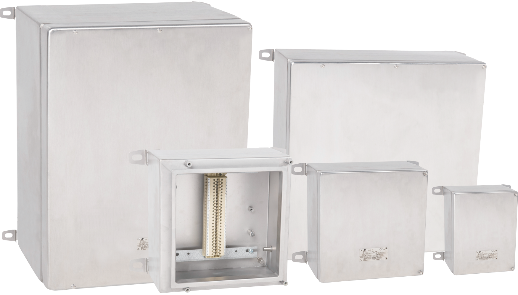
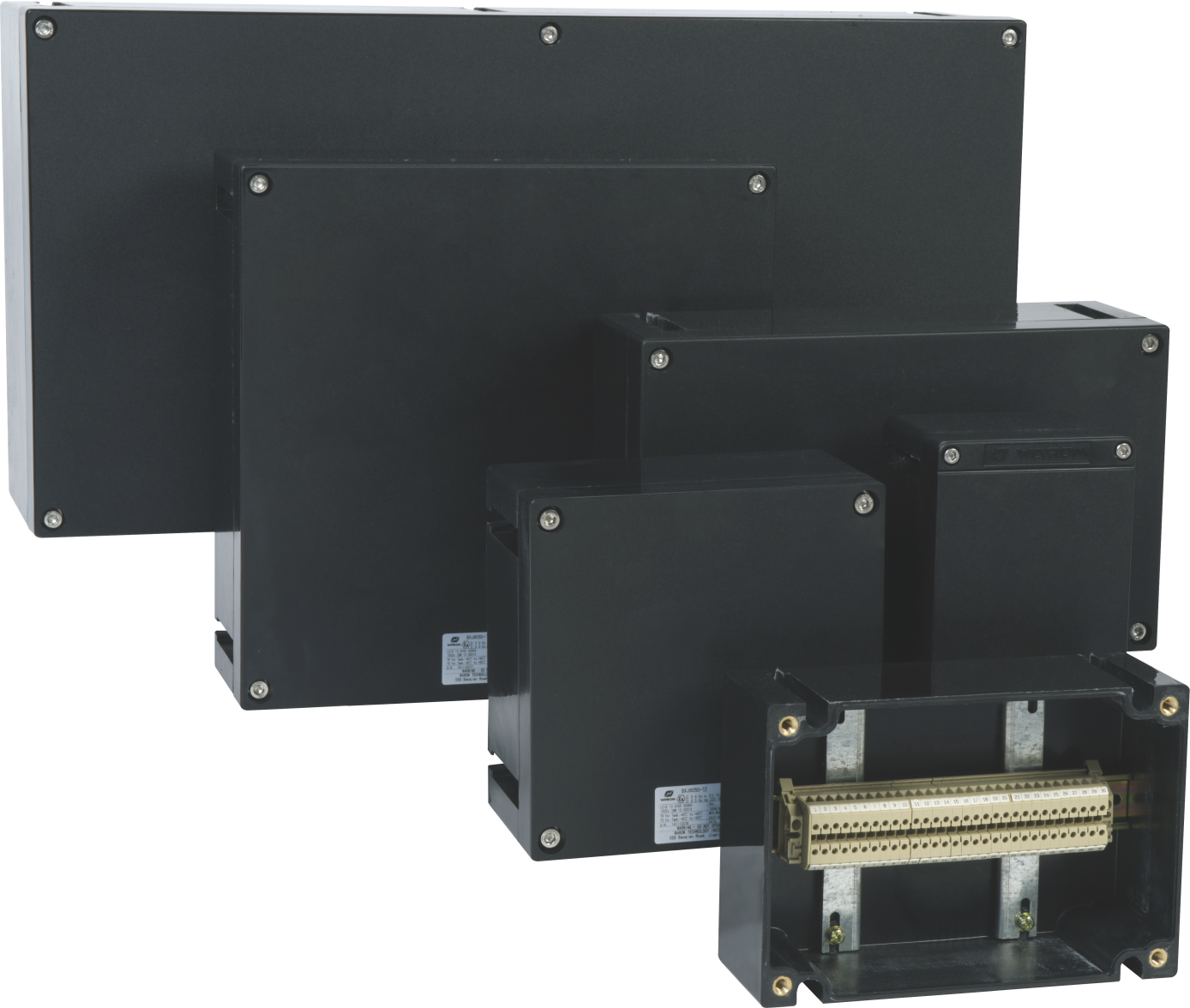
The same discipline applies to the rest of the loop. A terminal box, junction box, or local control station carries its own marking, its own certificate, and its own temperature class, and a circuit is only as compliant as its least-documented component.
How to Write the RFQ and Avoid Vague Specifications
Most quotation problems are specification problems. A supplier can only quote what the enquiry states, and an enquiry that names a zone and a signal will produce an instrument that meets a zone and a signal. The fields below are the ones that actually change the offered product.
| RFQ field | What to request | Why it matters |
|---|---|---|
| Area classification | Tank interior and instrument location classified separately, with gas group, temperature class, and required EPL | A single Zone 1 line hides a Zone 0 vapour space and invites a Gb-only instrument |
| Process data | Density, dielectric constant, viscosity, foam or emulsion tendency, operating and design temperature and pressure | A radar selected without dielectric data can lose the echo in low-dielectric hydrocarbons |
| Process connection | Flange standard, size and rating, insertion length, wetted material | A mismatched flange standard forces an adapter that changes insertion depth and the earth path |
| Certification regime | ATEX, IECEx, NEC, or a national scheme, with the certificate form the project accepts | Certificates in the wrong regime are rejected at goods receipt or at commissioning |
| Output and function | 4-20 mA, HART, fieldbus, switch type, SIL claim, and whether the overfill function must be independent | A SIL-capable sensor in a non-SIL loop leaves the safety function unproven |
| Documentation set | Datasheet with marking, certificate copy, schedule of limitations, test record, tag plate content | A missing schedule of limitations is where installation conditions get overlooked |
One rewrite does most of the work. An enquiry line such as the one below is common and almost unanswerable without assumptions.
Reject this RFQ line: “Explosion proof level transmitter, Zone 1, 24 VDC, 4-20 mA.” Replace it with: “Level transmitter for a fixed-roof tank, wetted parts 316L stainless steel, process connection DN80 PN16, product with a stated dielectric constant, tank interior classified Zone 0, transmitter head in Zone 1, gas group IIA, temperature class T4 minimum at 55 °C ambient, EPL Ga for the probe and Gb for the head, ATEX and IECEx certificates with the schedule of limitations, 4-20 mA with HART, SIL 2 capable for the overfill function, tag plate to the project data sheet.”
The specification work does not stop at the instrument, because the tank package also has to survive a design review by the contractor and the end user. <Specifying Explosion-Proof Electricals for EPC Projects: Safety & Compliance> covers how explosion-proof electricals are specified for EPC projects and the safety and compliance points that come up in that review.
Documentation is easier to keep aligned when the reference numbers on the instrument, the terminal box, and the drawing match. A terminal box ordered with the same project tag and the same marking convention removes a reconciliation step at goods receipt, which is where mismatches between a certificate and a delivery are usually found.
Commissioning Checks for Explosion Proof Level Instruments
Commissioning is the last point at which a mismatch is cheap to fix. The checks below follow the order in which they can be closed on site.
- Compare the marking on the instrument with the certificate and with the current area classification drawing. If the drawing has been revised since the order was placed, close the difference before installation rather than after.
- Confirm the cable entry device matches the protection concept. A flameproof housing needs a certified flameproof entry, and an intrinsically safe circuit still needs the gland type and screen termination shown on the loop drawing.
- Recalculate the intrinsically safe loop using the actual barrier or isolator, the actual instrument, and the actual cable, including capacitance and inductance [3].
- Check earthing and bonding. The instrument, the tank shell, and the associated pipework should share a defined earth reference, and the bonding result belongs in the inspection record.
- Verify the process connection. Gasket material, torque, and insertion depth should match the datasheet, and the probe should clear mixers, heating coils, and the tank floor.
- Configure the instrument against the datasheet: range, damping, alarm setpoints, and, where specified, the independence of the high-high function.
- Record a baseline. A stored echo curve for radar, a dry calibration record, or an output reading at a known level gives the next inspection something to compare against.
- Set the inspection interval and record the first inspection result [9].
Inspection grades differ. IEC 60079-17 separates visual, close, and detailed inspection, and the grade determines whether the instrument is checked in service, with the cover removed, or with the enclosure opened and the flame path examined [9]. The interval belongs to the site and should reflect the zone, the corrosivity of the environment, the age of the equipment, and the history of that specific installation.
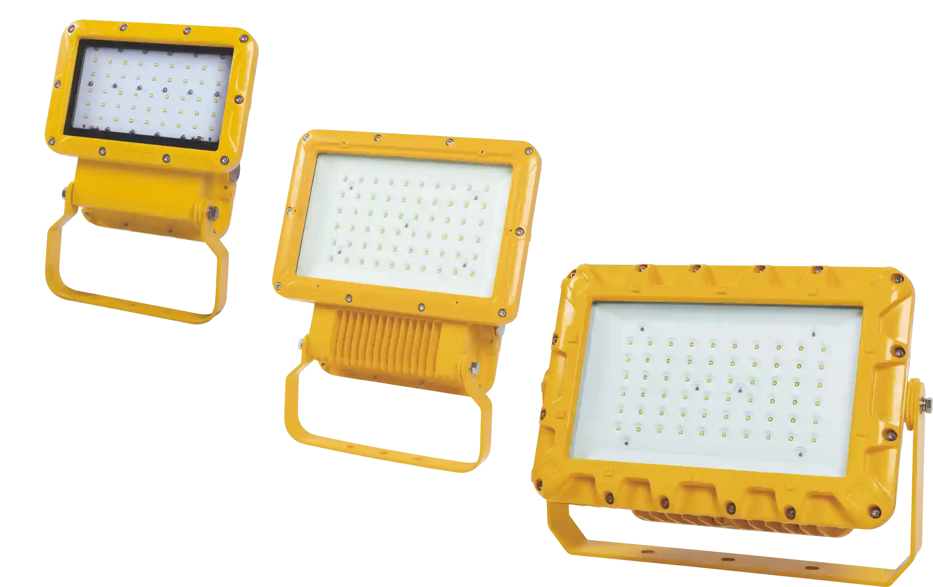
Two site conditions are easy to overlook because they sit outside the instrument. Access lighting matters when a technician has to read a local indicator or a tag plate on a tank roof, and that lighting must be rated for the same zone as the equipment it illuminates.
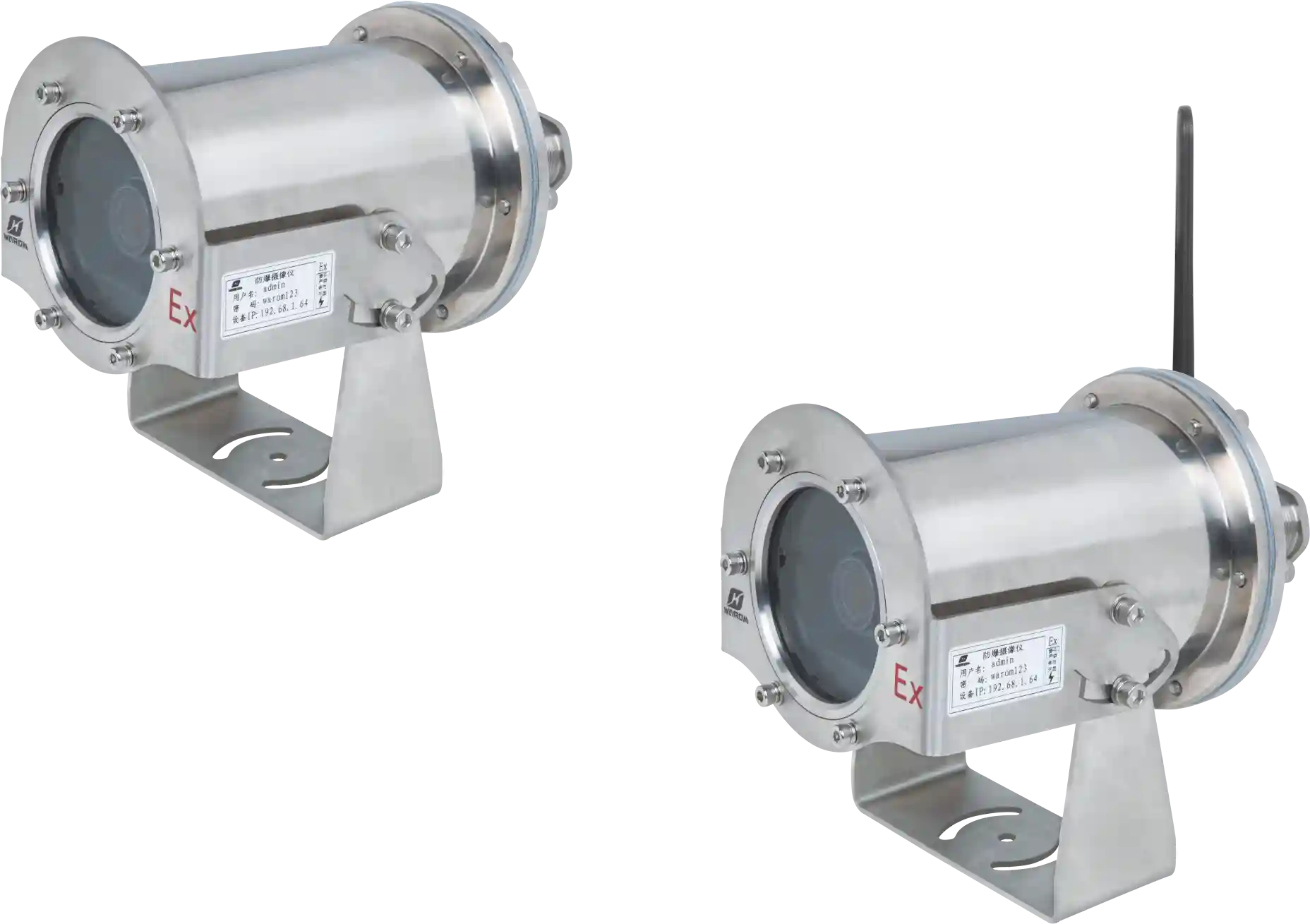
Remote monitoring is the other. Where tank gauging is watched from a control room, the camera and network equipment in the field need their own certification and their own segregation from the instrument loop, so a fault in one system does not travel into the other.
Send Your Tank Data for a Certificate and Loop Review
If a tank farm specification is still open, the fastest way to close it is to send data rather than a product name. Send the tank service and dimensions, the area classification reference, the gas group and temperature class for both the tank interior and the instrument location, the process temperature and pressure, the wetted material requirement, the required output and SIL claim, and the certification regime the project accepts. WAROM Technology supplies explosion-proof electrical equipment for tank farm and process installations, and our engineers will check the proposed marking and protection concept against that data and tell you what is still missing. Email gm*@***om.com or call +86 21 39977076 or +86 21 39972657.
FAQ
Does a level sensor need Zone 0 approval if the tank is normally full?
The classification does not depend on how full the tank usually is. Zone 0 describes a space where a flammable atmosphere is present continuously, for long periods, or frequently [1]. In a fixed-roof tank holding a volatile product, the vapour space above the liquid is often assessed as that kind of space, and a high working level does not remove it. Where the assessment places the vapour space in Zone 0, the wetted part needs EPL Ga, which is why many installations use a split design with a passive probe in the tank and the transmitter head outside it.
Is flameproof Ex d better than intrinsically safe Ex ia for tank instruments?
Neither is better in general; they solve different constraints. Flameproof contains an internal explosion and permits ordinary energy levels inside the enclosure, but it depends on certified entries and flame path maintenance and is not accepted for Zone 0 equipment [2], [4]. Intrinsic safety keeps energy below ignition levels and suits a probe inside the tank, but it needs a barrier or isolator and a loop calculation that includes the cable [3]. Choose by zone, by what the measurement technology allows, and by how the site will maintain the loop.
Will an ATEX certificate be accepted for an IECEx project?
Not automatically. ATEX is the legal route for placing equipment on the EU market, while IECEx is a separate international certification scheme, and the two produce different marking strings and documentation [8]. Some project specifications accept either, some name one scheme, and some require a national scheme in addition. Confirm which regime the buyer, insurer, or authority will accept before the order, because a certificate in the wrong regime is usually discovered at goods receipt.
How often should explosion proof level sensors be inspected?
The interval is set by the site, not by the instrument datasheet. IEC 60079-17 defines visual, close, and detailed inspection grades and leaves the frequency to a schedule based on the zone, the environment, the equipment type, and service history [9]. A sensor in a coastal tank farm with corrosive vapour and frequent access will normally need a shorter interval than one in a dry, clean, rarely opened installation. Record the first inspection result and let it adjust the second interval.
Do I need a SIL-rated level sensor for overfill protection?
Only if the overfill function is designated a safety instrumented function in the site risk assessment. IEC 61508 provides the framework for the SIL claim [6], but the required level comes from the risk assessment and the achieved level belongs to the whole loop, including the logic solver, the final element, and the proof-test interval. A SIL-capable sensor installed in a loop that is never proof tested provides documentation, not protection.
References
[1] IEC 60079-10-1:2020, “Explosive atmospheres – Part 10-1: Classification of areas – Explosive gas atmospheres,” International Electrotechnical Commission, Geneva, 2020.
[2] IEC 60079-0:2017, “Explosive atmospheres – Part 0: Equipment – General requirements,” International Electrotechnical Commission, Geneva, 2017.
[3] IEC 60079-11:2011, “Explosive atmospheres – Part 11: Equipment protection by intrinsic safety ‘i’,” International Electrotechnical Commission, Geneva, 2011.
[4] IEC 60079-1:2014, “Explosive atmospheres – Part 1: Equipment protection by flameproof enclosures ‘d’,” International Electrotechnical Commission, Geneva, 2014.
[5] IEC 60079-14:2013, “Explosive atmospheres – Part 14: Electrical installations design, selection and erection,” International Electrotechnical Commission, Geneva, 2013.
[6] IEC 61508-1:2010, “Functional safety of electrical/electronic/programmable electronic safety-related systems – Part 1: General requirements,” International Electrotechnical Commission, Geneva, 2010.
[7] IEC 60529:1989+AMD1:1999+AMD2:2013, “Degrees of protection provided by enclosures (IP Code),” International Electrotechnical Commission, Geneva, 2013.
[8] Directive 2014/34/EU, “On the harmonisation of the laws of the Member States relating to equipment and protective systems intended for use in potentially explosive atmospheres,” Official Journal of the European Union, 2014.
[9] IEC 60079-17:2013, “Explosive atmospheres – Part 17: Electrical installations inspection and maintenance,” International Electrotechnical Commission, Geneva, 2013.
If you’re interested, check out these related articles:
The “Canton Fair” blooming “WAROM” style
Wonderful Appearance in China International Maritime Exhibition
With over a decade of experience, he is a seasoned Explosion-Proof Electrical Engineer specializing in the design and manufacture of safety and explosion-proof products. He possesses in-depth expertise across key areas including explosion-proof systems, nuclear power lighting, marine safety, fire protection, and intelligent control systems. At Warom Technology Incorporated Company, he holds dual leadership roles as Deputy Chief Engineer for International Business and Head of the International R&D Department, where he oversees R&D initiatives and ensures the precise delivery of design documentation for international projects. Committed to advancing global industrial safety, he focuses on translating complex technologies into practical solutions, helping clients implement safer, smarter, and more reliable control systems worldwide.

Qi Lingyi