

Explosion proof distribution cabinets with energy metering create a coordination problem before they ever create a data point. Operations wants consumption data, the instrumentation team wants signals, and the electrical team has to keep every circuit inside a certified enclosure. The answer is not to add a standard panel meter after the cabinet design is frozen. Metering must be designed into the Ex d or Ex e enclosure from the single-line diagram forward because current transformer location, voltage tapping, communication wiring, and temperature class all interact. This article covers the decisions I ask engineering teams to fix before drawings go out rather than after a factory acceptance test exposes a fit issue.
Energy Metering Functions Inside an Explosion Proof Distribution Cabinet
An energy meter in a hazardous area cabinet is not a display bolted to the door. It is a measurement circuit that changes how the enclosure is laid out. The meter receives current signals from current transformers and voltage references from the bus or cable entries, then converts them into energy values, demand readings, or pulse outputs. Every one of those connections has to respect the same flamepath, creepage, and temperature limits as the power circuit. If the meter goes behind a viewing window, the window becomes part of the certified enclosure system. If the meter is blind, the maintenance team needs another way to read data, usually through a communication link.
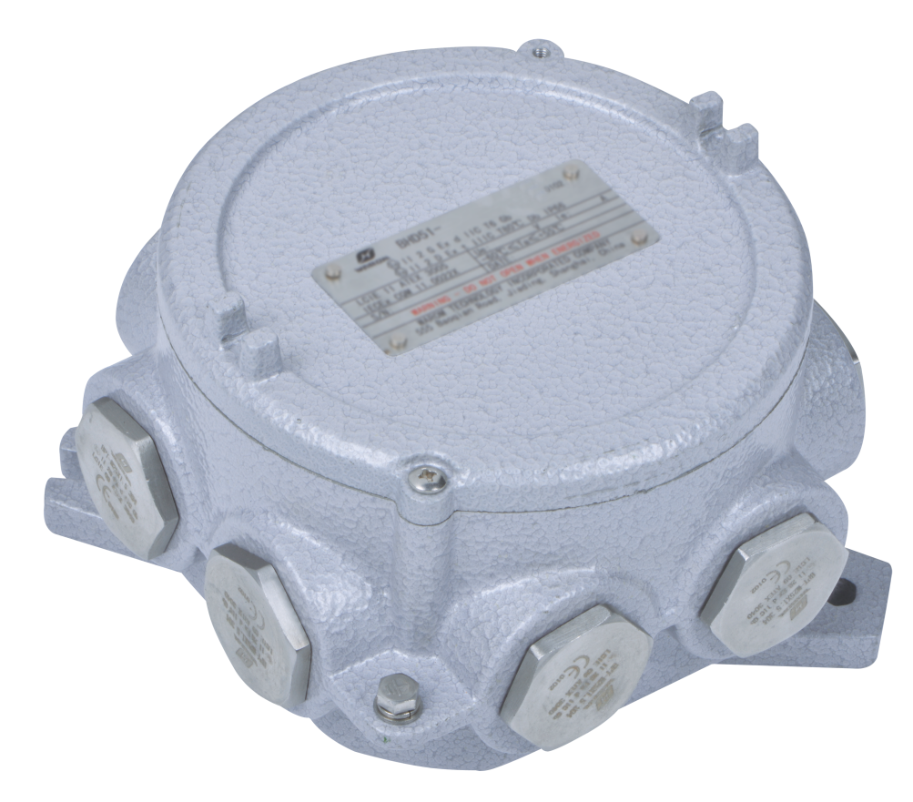
Before layout starts, I fix the following parameters with the client or EPC:
| Metering element | What to lock in the specification | Interaction inside the certified enclosure |
|---|---|---|
| Current transformers | Ratio, burden, accuracy class, short-time current | CT size and bending radius consume enclosure volume and add heat rise |
| Voltage reference | Phase-to-phase or phase-to-neutral, fuse protection | Voltage wiring must be segregated from control and communication circuits |
| Metering device | Accuracy class, display or blind unit, protocol | The device fits behind a certified window or inside a separate Ex e compartment |
| Communication module | RS485 Modbus RTU, Ethernet, or pulse output | Additional module changes gland count, barrier type, and signal segregation |
| Auxiliary power | 24 V DC or 230 V AC, UPS where required | Auxiliary supply adds heat load and must be included in the T class calculation |
| Enclosure access | Viewing window, hinge door, field-termination access | Window and door sealing must preserve the original protection method |
Each of these choices changes the number of cable glands, the terminal compartment layout, and the thermal calculation.
Metering Input Specifications and Accuracy Class Decisions
The metering circuit is only as stable as the instrument transformer feeding it. I would rather reduce the number of unverified assumptions here than anywhere else in the cabinet. A meter with a 0.5S accuracy class loses meaning if the CT burden is too high or if the voltage reference is taken from the wrong side of a protection element.
Current transformer ratio, burden, and short circuit rating
We specify the CT ratio from the maximum expected load, not from the breaker frame alone. A 400 A frame with a 100 A connected load needs a 150/1 A or 200/1 A CT if anyone expects meaningful low-load readings. The burden declared by the meter manufacturer must be added to the wiring loop impedance between CT and meter. Long secondary runs inside the cabinet, or runs to a separate metering compartment, can push the burden above the CT class limit. The CT short-time thermal current must also be checked against the upstream protective device because a CT that saturates under fault conditions will not destroy the meter but may produce false readings until it settles.
Voltage connection, fusing, and segregation
Voltage inputs should be fused close to the tapping point. In an Ex e enclosure, voltage wiring cannot share a duct with communication or instrument cables unless the segregation rules for the protection method permit it. I prefer a dedicated terminal row for metering voltage with a separate fuse, sized to the meter’s input impedance, not to the branch load. That fuse protects the meter input from a backfeed or a downstream fault without interrupting the main circuit.
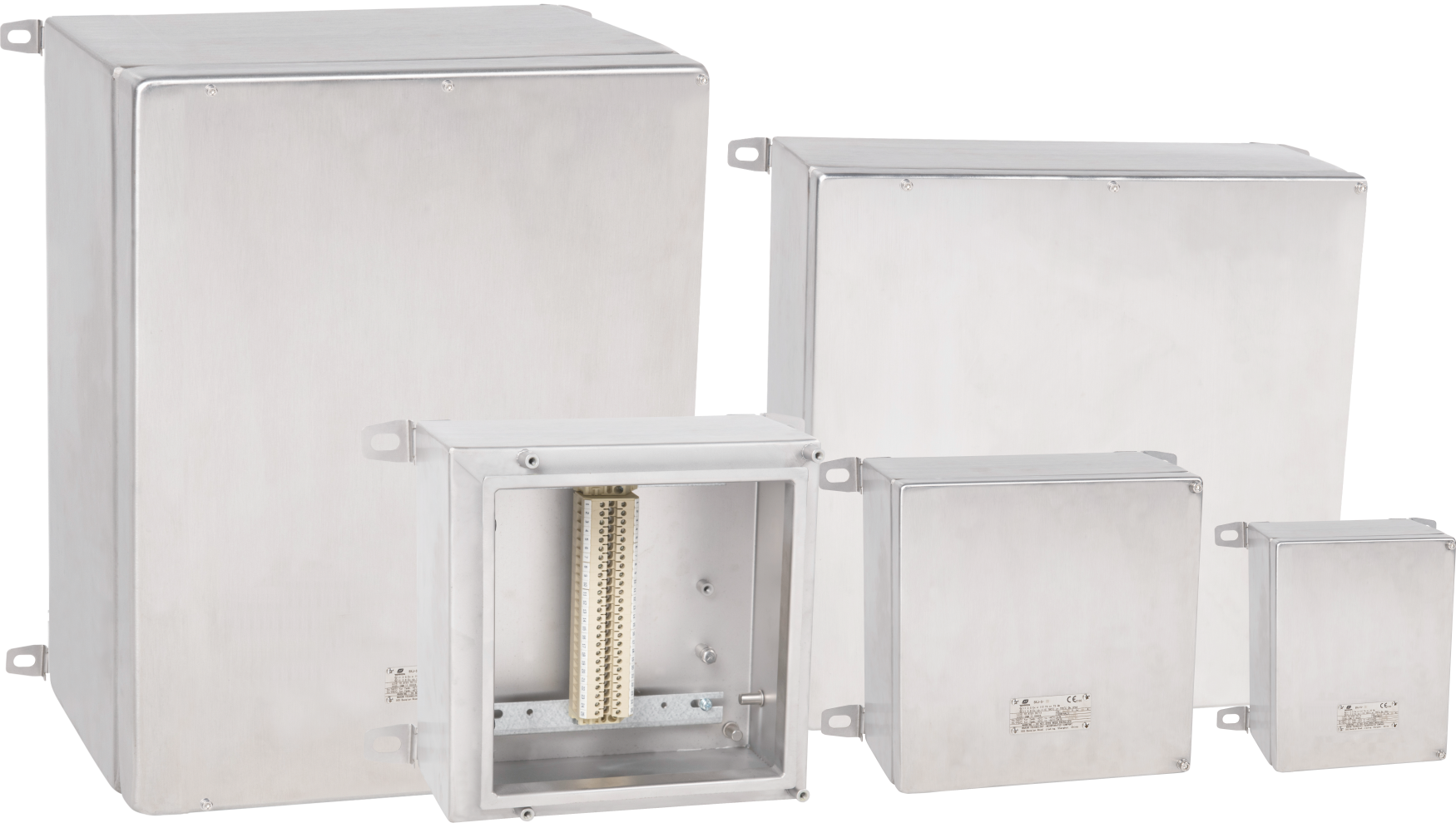
Accuracy class and scaling verification
Class 0.5S is often specified for revenue or contract billing, while class 1 is enough for internal energy allocation. The important step is scaling verification during commissioning. If the CT ratio, PT ratio, and meter settings are not matched at the same time, the displayed energy value can be off by the transformer ratio. We check this with a known load at factory test and again during site commissioning before the panel is sealed.
Communication, Wiring, and Certification Requirements for Metered Cabinets
Adding metering changes the thermal budget. A 10 W meter and its power supply may not sound like much, but inside a sealed flameproof enclosure in a 50°C ambient, 10 W can raise the internal temperature enough to affect the T class margin. We include the meter, auxiliary supply, and communication electronics in the thermal calculation. If the enclosure is already close to its temperature class limit, the answer may be a separate Ex e metering chamber or a larger enclosure, not a larger cooling loop.
Since metering equipment often shares the cabinet with motor isolation devices, the disconnector arrangement affects the space available for CTs and terminal rows. <Explosion Proof Motor Disconnects: ATEX and NEC Compliance> explains the protection-method differences that determine whether the disconnector sits in a flameproof chamber or an Ex e compartment, which is the same layout choice that governs metering volume.
Wiring segregation is the next constraint. Metering voltage wires, communication conductors, and power cables cannot be mixed in the same trunking without checking the standard for the specific protection method. In Ex e systems, clearance and creepage distances determine terminal spacing. The meter’s RS485 cable should not run parallel to power conductors through the full cabinet. If it must cross, it should cross at right angles or through a grounded divider. These rules are not installation niceties. They are the conditions recorded in the certification file.
A practical check before specifying communication is to confirm which party owns the metering data. If the site SCADA expects a Modbus register map and the panel builder only supplies pulse outputs, commissioning stalls. Send your SCADA point list to gm*@***om.com before the communication module is frozen.
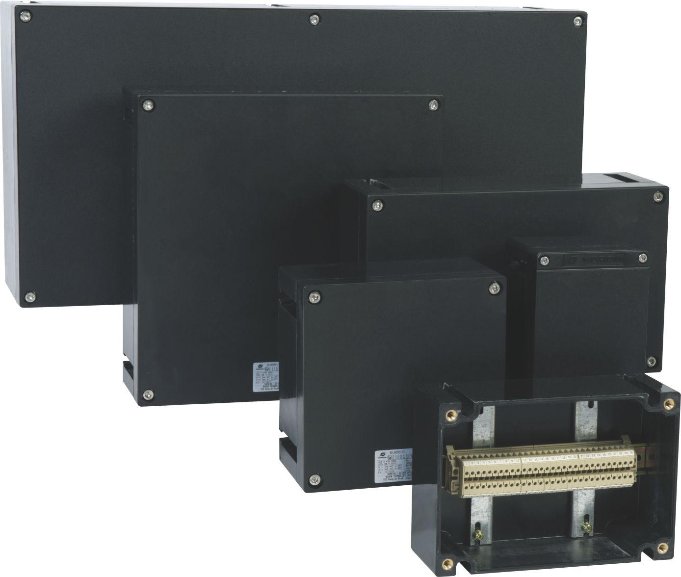
Warom’s BXM(D)8050 illumination distribution boxes show why modular construction matters. They combine Ex d and Ex e chambers in one enclosure, which gives a defined place for the meter behind a flameproof window and the terminals in the increased safety chamber. The same modular logic applies when the meter is blind: communication modules sit in an Ex e terminal compartment, and the flameproof chamber stays reserved for the switching or metering element that requires it.
Factory Testing and Documentation for Energy Metered Cabinets
A metered cabinet has two test sequences. The first verifies the enclosure, flamepaths, creepage, and ingress protection. The second verifies CT polarity, ratio, scaling, and communication registers. I want both witnessed before shipment, not because a cabinet cannot be corrected later, but because corrections on site cost more than any factory rework. If the incorrect CT polarity is discovered after installation, the panel build is already complete and the meter will read reverse power until a site electrician opens the certified enclosure.
On the Tilenga project in Uganda, the electrical systems covered wellpads, the central processing facility, and pipelines under extreme conditions with low maintenance and zero safety incidents. A metered cabinet should meet the same standard: the data path has to survive commissioning without repeated opening of a certified enclosure. That only happens when the drawing package includes the CT location, the register map, and the metering point list before production.
Confirming the Metered Cabinet Design
Energy metering inside a flameproof or increased safety cabinet creates coordination between the electrical, instrumentation, and certification scopes. A mistake found at site commissioning costs more than a drawing review at the start. Send your single-line diagram, connected load, hazardous area classification, and meter point list to gm*@***om.com or call +86 21 39977076 / +86 21 39972657. We will confirm CT burden, scaling, communication mapping, and enclosure layout before the cabinet enters production, so the final factory acceptance test has no unresolved metering issues.
Common Questions About Explosion Proof Distribution Cabinets with Energy Metering
Can a standard panel energy meter be installed inside an explosion proof distribution cabinet?
A standard panel energy meter cannot be placed inside a certified hazardous area enclosure unless the meter carries the appropriate Ex marking or sits behind a certified flameproof window. The better route is to design the meter into the certified enclosure from the start. If the meter is blind, a communication output through an Ex e terminal compartment is usually simpler and avoids weakening the door with a large viewing window.
Does energy metering affect the cabinet temperature class?
Only when the temperature class margin is already tight. A meter and its auxiliary power supply add continuous heat to the sealed enclosure. If the T class margin is small, the internal temperature calculation may push the equipment into the next lower temperature class. We include all active devices in the thermal assessment before ordering, and if the margin cannot be recovered, we specify a lower-power meter or move the electronics into a separate Ex e chamber.
What is the difference between Class 0.5 and Class 0.5S meters in hazardous area cabinets?
The difference shows up at low current, not at full load. A Class 0.5S meter maintains its stated accuracy across a wider low-current range, which matters when the load runs below 20 percent of the CT rating. A plain Class 0.5 meter is enough for many internal checks, but if the cabinet supplies a tenant, an intercompany meter, or a contract billing point, 0.5S is the safer choice. The cost increase is small compared with a disputed energy reading.
How do we confirm the correct CT ratio and communication map before ordering?
Send the single-line diagram, connected load, and SCADA register list. We will confirm CT ratios, meter scaling, and which communication output fits the certified cabinet without weakening the enclosure. We also check the CT burden against the secondary wiring length and the meter input impedance, because those details decide whether the panel metering loop is stable from day one. Share your requirements with gm*@***om.com or call +86 21 39977076 and we will return the metering specification with the main distribution cabinet quotation.
If you’re interested, check out these related articles:
Balikpapan Industrial Expo – BEX
WAROM to Exhibit at Oil & Gas Asia Kuala Lumpur 2025
WAROM at NOG ENERGY WEEK
OGI 2024 Jakarta is underway
Explosion Proof Emergency Exit Light Fittings for Industrial Safety
With over a decade of experience, he is a seasoned Explosion-Proof Electrical Engineer specializing in the design and manufacture of safety and explosion-proof products. He possesses in-depth expertise across key areas including explosion-proof systems, nuclear power lighting, marine safety, fire protection, and intelligent control systems. At Warom Technology Incorporated Company, he holds dual leadership roles as Deputy Chief Engineer for International Business and Head of the International R&D Department, where he oversees R&D initiatives and ensures the precise delivery of design documentation for international projects. Committed to advancing global industrial safety, he focuses on translating complex technologies into practical solutions, helping clients implement safer, smarter, and more reliable control systems worldwide.

Qi Lingyi