

Predictive maintenance in a classified area fails when monitoring hardware cannot survive the same atmosphere it is supposed to watch. Explosion proof condition monitoring is not just a vibration sensor with a certificate; it is the complete loop of sensors, cable glands, junction boxes, barriers, and data connections that keeps a signal safe from the field to the control room. In more than thirty years of explosion-proof electrical work, I have seen too many plans treat the sensor as the project and the installation as an afterthought. That approach strands useful data and weakens the safety case.
What Explosion Proof Condition Monitoring Actually Measures
Condition monitoring in Ex areas spans vibration, temperature, pressure, gas concentration, and sometimes visual or thermal imaging. Each channel catches a different failure mode. Vibration picks up bearing distress, imbalance, misalignment, and gear wear. Temperature catches overloaded motors, failing terminations, and blocked cooling paths. Pressure and gas monitoring catch seal leaks, relief events, and combustible gas accumulation. Visual and thermal imaging add a useful overview for switchgear and terminations. 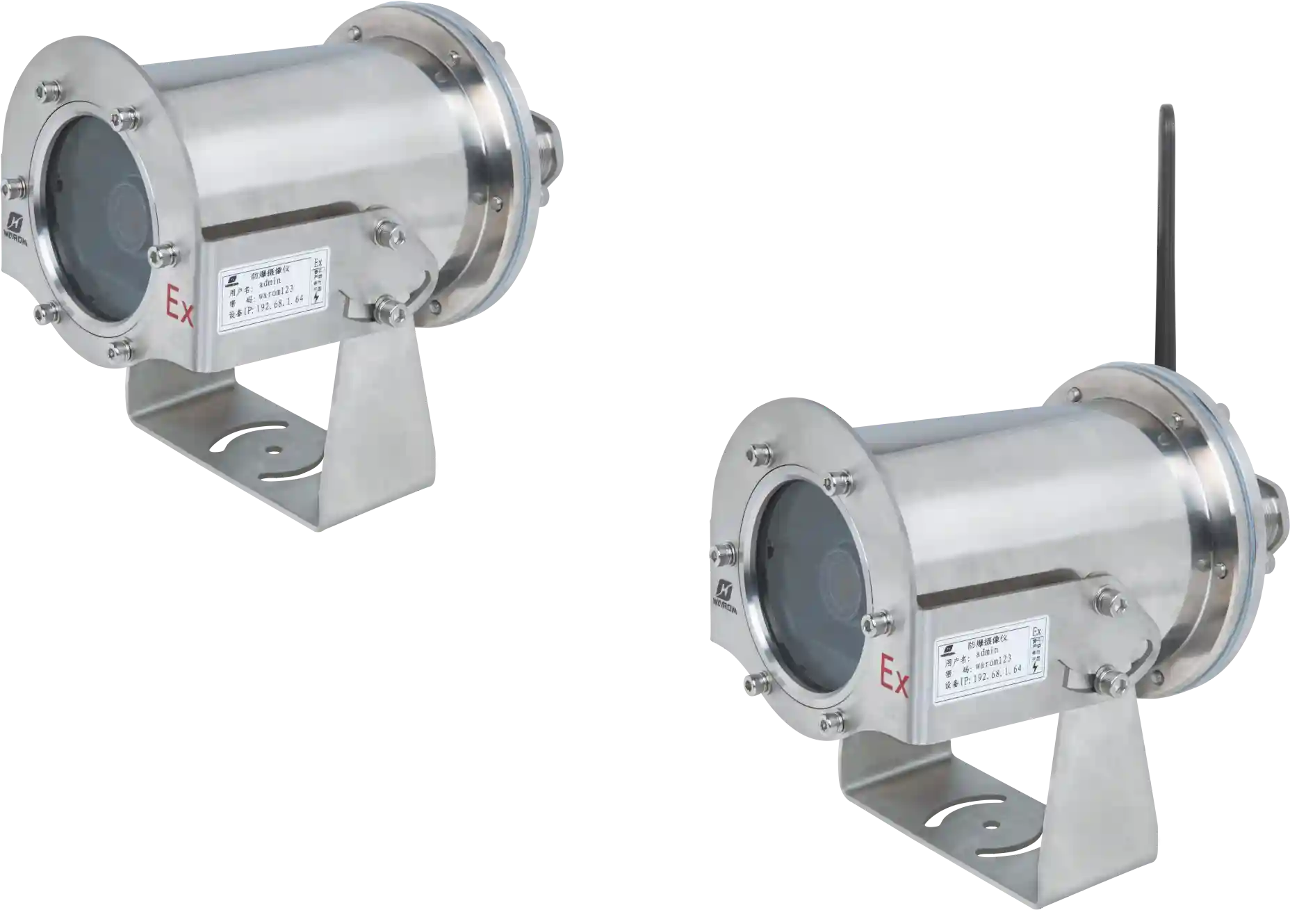
A plant that monitors only one channel catches only one failure mode, and predictive maintenance programs built on a single signal fail more often than buyers expect.
What Does Vibration Data Reveal Before a Bearing Fails?
Vibration is the earliest warning for most rotating equipment. A bearing will show high-frequency energy long before it becomes hot or noisy. In Zone 1 and Zone 2 areas, the accelerometer, its cable, and the signal conditioner all sit inside the hazardous classification. The sensor housing must meet the area protection method, and the cable gland must preserve the flamepath or increased safety. If the sensor passes its certificate but the wiring is not compliant, the reading may be valid but the loop is not.
Why Temperature Is a Confirmation Signal, Not an Early Warning
Temperature tends to rise after mechanical damage has already begun. A motor bearing that is shedding metal will eventually show a hotter housing, but waiting for temperature moves you closer to an unplanned shutdown. In coal conveyor and other material handling applications, operators often use surface temperature as a cheaper proxy and miss the first stage of bearing wear. Gas detection plays a different role. It is usually a process safety function rather than an equipment health function.
Conveyors concentrate this issue because accessible measurement points often sit outside the certified enclosure. <Explosion Proof Solutions for Coal Conveyor Safety> covers how dust classification, enclosure placement, and mechanical guarding combine in coal handling areas, and why surface temperature alone is rarely enough for an early warning.
How to Choose Condition Monitoring Devices for Zone 1 and Zone 2
Zone 1 and Zone 2 push the selection decision beyond sensor accuracy. The protection method matters as much as the measurement range. A vibration accelerometer can be an intrinsically safe Ex ia device, a flameproof Ex d device, or a less protected Ex nA device only where the classification permits. The same logic applies to temperature transmitters, pressure transmitters, gas detectors, and fixed thermal cameras.
| Monitoring device | Typical protection method | Best use in hazardous area |
|---|---|---|
| Vibration accelerometer | Ex ia or Ex d | Motors, gearboxes, pumps, fans |
| Surface temperature sensor | Ex d terminal head or Ex e | Bearings, motor housings, seal chambers |
| Gas detector | Ex d or Ex ia | Leak detection, LEL and toxic gas alarm |
| Pressure transmitter | Ex d or Ex ia | Pump discharge, seal systems, process lines |
| Fixed thermal camera | Ex d housing | Switchgear, terminations, mechanical joints |
Explosion proof condition monitoring selection starts with the zone, then narrows by gas group, dust group, and temperature class. A motor housing already near its temperature class leaves no margin for a sensor head that adds heat. In practice, I have seen buyers approve a device list before checking the T class, then rework the entire loop.
The sensor choice and the cable entry should be made as one decision, not separate bids. <NPT Explosion Proof Cable Glands for US & Middle East Projects> covers why NPT entries, sealing requirements, and mixed US and IEC specifications often create site-level problems when North American and Middle East requirements appear in the same package.
Connection points multiply when a single motor has vibration, temperature, and pressure sensors feeding one junction box. 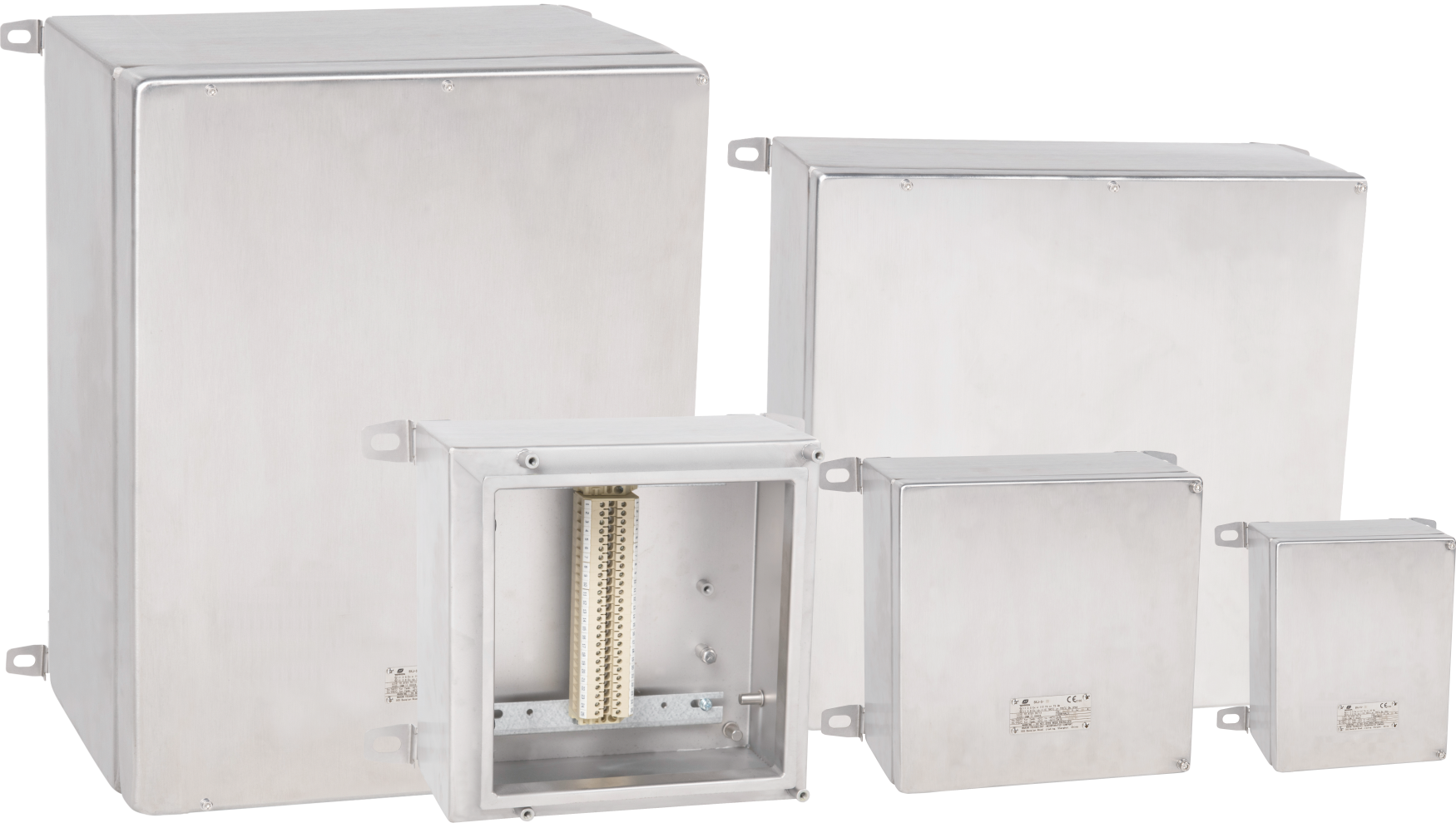
Mixed sites are where we see the most preventable specification failures. A location list that combines Zone 1 gas, Zone 21 dust, and North American conduit entry often cannot be served by one product range. Before you finalize the bill of materials, send your zone map and measurement point list to gm*@***om.com and we will confirm the protection methods, gas groups, temperature classes, and entry types that apply to each location.
What Goes Wrong When the Data Path Is Not Explosion Proof
The sensor is the simple part. Many explosion proof condition monitoring failures we review start outside the sensor, in the cable entry, the junction box, the barrier, or the earthing arrangement.
A certified accelerometer does not create a certified loop. The 4-20 mA or digital signal has to pass through glands, terminals, maybe a surge protector, and an isolation barrier before it reaches a DCS, PLC, or historian. Any one of those points can turn a good signal into a drifting, noisy, or lost channel.
Moisture ingress through an unused entry is the most common physical fault. 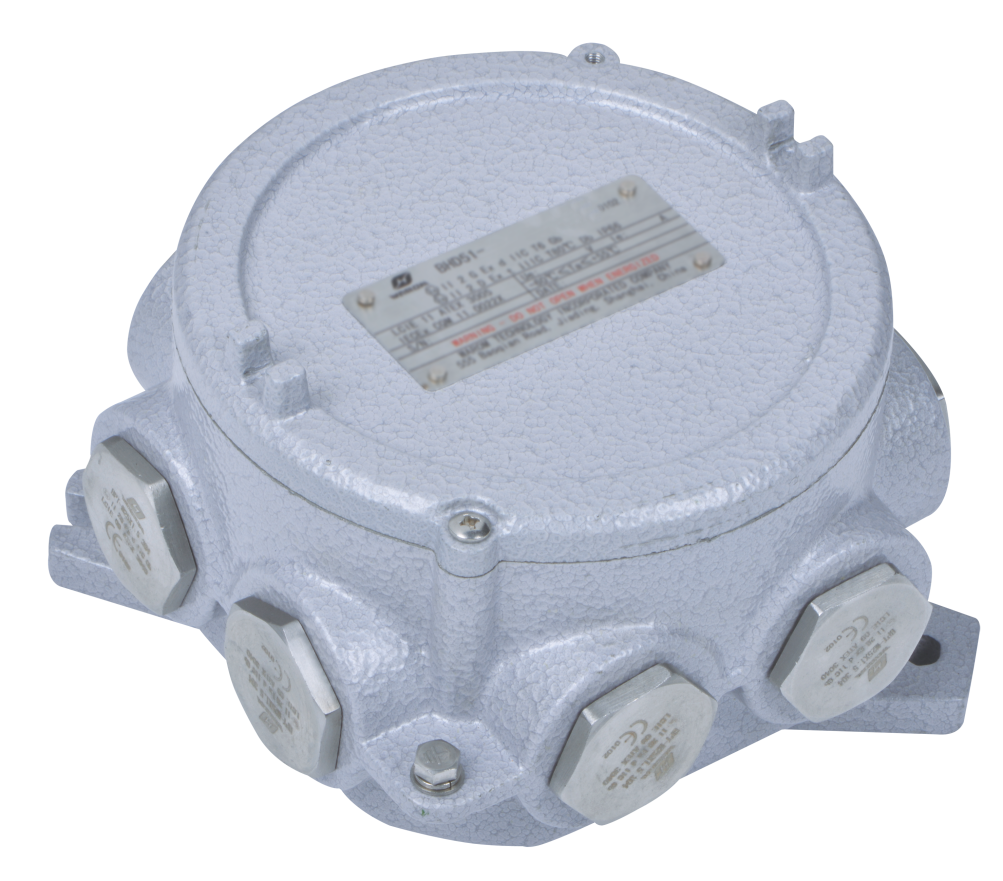
In one repeated pattern across oil and gas projects, a junction box in a coastal or humid location takes in water through a temporary plug. The first sign is usually a drifting 4-20 mA signal, not a visible fault. By the time the box is opened, terminal corrosion has already begun. I have also seen shield drain wires connected on both ends, which creates a ground loop that shifts the measurement. Those failures are not sensor failures, but they disable predictive maintenance just the same.
Signal barriers add another layer. An intrinsically safe barrier changes loop resistance and may limit available power, which matters for multi-sensor fieldbus or wireless gateways. The loop must be verified with the barrier installed, not calculated from the sensor datasheet alone.
How to Build an Explosion Proof Predictive Maintenance Specification That Survives an Audit
Most audit failures happen because the specification was written as a product list rather than a loop design. A stronger approach starts with the site classification and works outward. Use these five steps.
- Start with the zone map, gas group, dust group, and temperature class for each measurement point.
- Define the loop for each channel: sensor, cable, gland, junction box, barrier or isolator, and control room input.
- Require certificates for the complete loop, including glands, boxes, and barriers, not only the sensor.
- Test loop accuracy after installation with the barrier or isolator in place.
- Plan maintenance access so that opening an enclosure is not the only way to check a signal.
A specification built this way also makes supplier comparison easier. When two vendors quote different device sets, the loop design shows which one has accounted for the harder boundary points. Supplier quality at those boundary points matters as much as the sensor brand.
Supplier quality affects loop life because terminal integrity and seal quality are factory processes. <Improve Product Quality And Be A Good Safety Guard> covers how quality control and safety assurance work together in production, which matters when a monitoring junction box has to remain sealed for years in a dusty or coastal environment.
Predictive maintenance in a classified area is an engineering decision, not a sensor purchase. The most accurate vibration transmitter is worth little if its cable entry weakens the enclosure or its signal cannot cross the barrier without distortion. If you are writing a condition monitoring specification for a refinery, LNG terminal, coal handling plant, or solvent area, send the zone map, equipment list, and preferred communication protocol to Warom at gm*@***om.com or call +86 21 39977076 +86 21 39972657. We will review the loop architecture and confirm which protection methods, temperature classes, and cable entries fit before you commit to a bill of materials.
What Do Buyers Ask About Explosion Proof Condition Monitoring?
Can I use a standard wireless vibration sensor outside the enclosure in a classified area?
No, unless the sensor carries the certification required for the zone and the wireless device is approved for that location. Zone 1 equipment must meet recognized protection methods such as Ex ia or Ex d, and Zone 2 allows limited Ex nA or Ex ec designs where the area classification and local code accept them. A non-certified wireless node may be convenient, but it becomes a potential ignition source and a compliance gap. Wireless battery changes in solvent or dust areas also require a controlled work permit.
Does an Ex certificate mean the equipment is intrinsically safe?
That is a common misunderstanding. An Ex certificate confirms protection method compliance, not intrinsic safety. Ex ia and Ex ib are intrinsically safe; Ex d uses a flameproof enclosure; Ex e and Ex ec use increased safety; Ex nA or Ex nC use non-sparking or protected construction. The marking on the nameplate states which protection method applies. Buyers should match the protection method to the zone, not assume that any Ex label allows live maintenance or simple wiring.
Do dust areas need explosion proof condition monitoring too?
It depends on the classification and the material being produced. Zone 21 and Zone 22 dust environments carry their own ignition risks, and condition monitoring devices in those areas should meet the dust group requirements on the certificate. Conveyors, mills, and silos often combine a dust hazard with rotating equipment, so the monitoring loop has to close both the gas and dust certification boundaries. If the location is classified for dust only, choose devices with the correct Ex tb or equivalent dust marking and a compatible enclosure.
What causes most condition monitoring loop failures in hazardous areas?
In the condition monitoring loops we have reviewed, cable entry and gland sealing problems cause more signal drift than sensor electronics. Water enters through unused entries, shield connections form ground loops, and barriers installed later shift loop resistance. The sensor may still be healthy, but the data becomes unreliable. The fix is usually at the boundary, not at the transmitter. If your program is moving from pilot to full deployment, share the loop schematic and installation photos with gm*@***om.com and we will confirm where the certified boundary and the signal boundary actually sit.
If you’re interested, check out these related articles:
2025 Explosion Proof Lighting Standards: Compliance Guide
Warom Technology Shines CSSOPE 2024
Day 2 of Australian Energy Producers Conference & Exhibition 2025
Warom at 2025 ADIPEC
With over a decade of experience, he is a seasoned Explosion-Proof Electrical Engineer specializing in the design and manufacture of safety and explosion-proof products. He possesses in-depth expertise across key areas including explosion-proof systems, nuclear power lighting, marine safety, fire protection, and intelligent control systems. At Warom Technology Incorporated Company, he holds dual leadership roles as Deputy Chief Engineer for International Business and Head of the International R&D Department, where he oversees R&D initiatives and ensures the precise delivery of design documentation for international projects. Committed to advancing global industrial safety, he focuses on translating complex technologies into practical solutions, helping clients implement safer, smarter, and more reliable control systems worldwide.

Qi Lingyi