
Explosion-proof equipment for flare systems must do more than meet a gas group and temperature class on paper. It has to keep working while a flare stack radiates heat day and night, often with no shutdown window for maintenance. In three decades of specifying electrical equipment for these installations, I have learned that standard certified equipment, perfectly suitable for most hazardous areas, can degrade within months when mounted within the thermal radiation envelope of a continuously operating flare. This article identifies the zone classification logic, thermal management realities, and equipment requirements that shape real-world specification decisions for flare and vent header installations.
What Zone Classification Applies to Flare Systems and Vent Headers?
Zone classification around a flare stack is not a single number you pull from a table. The envelope around a flare system typically includes three distinct zones, and equipment selection differs for each.
The area immediately surrounding the flare tip—where unburned hydrocarbons may be present during ignition or flameout events—is generally classified as Zone 1. This extends outward in a radius determined by the flare stack height, gas composition, and predicted dispersion modelling under worst-case wind conditions. For high-pressure flares handling heavier hydrocarbons, the Zone 1 envelope can reach farther than many project engineers initially estimate.
Below and around the base of the flare stack, where the knockout drum, seal drum, and associated piping are located, the classification typically drops to Zone 2. This is where much of the electrical infrastructure sits: junction boxes for instrumentation, power distribution for ignition systems, and lighting for access platforms. The gas is normally absent here, but a release from a flange or instrument tap is credible.
Vent headers present a different challenge. Unlike flared gas, vented gas may be released cold and dense, pooling in low areas before dispersing. This creates secondary Zone 2 pockets that are easy to overlook during equipment layout planning. In our project work, we have mapped these with gas dispersion studies before finalizing cable gland positions and junction box elevations.
The key selection point: equipment located within the Zone 1 envelope must carry Ex d flameproof or appropriate protection concepts for IIC gas group. Equipment in Zone 2 can use Ex e increased safety or Ex n for non-sparking, but only if the thermal exposure is managed separately—the zone rating alone does not address heat.
How Thermal Radiation Affects Electrical Equipment Near Flare Stacks
This is where I see the most equipment failures in the field, and it has little to do with explosion protection. The problem is heat.
A typical hydrocarbon flare radiates significant thermal energy. At the design stage, a flare radiation analysis will give you heat flux contours in kW/m². Equipment within the 1.5–3.0 kW/m² band experiences surface temperatures far above ambient, and this accelerates polymer degradation in cable glands, reduces lubricant life in disconnect switches, and pushes electronic components toward their upper operating limits.
I have inspected installations where junction box gaskets, rated to 90°C, had hardened and cracked after eighteen months because the enclosure surface temperature was running at 85°C continuously—not from internal heat, but from absorbed radiation. The boxes were correctly certified. The gaskets were correct on the datasheet. But nobody had accounted for the 20°C temperature rise from standing in the flare’s radiation field.
For equipment near vent headers, the thermal load is lower but the temperature cycling can be worse. A cold vent release followed by a steam purge cycle can swing the enclosure temperature by 40°C in under an hour. That cycling stresses every seal and terminal connection.
Practical measures we specify now include radiation shields—simple stainless steel sheets mounted between the flare and the equipment rack—and selecting equipment with T5 or T6 temperature class even when T4 would satisfy the gas group. The extra thermal margin gives you operating headroom. For cable glands in elevated-temperature areas, we specify nickel-plated brass DQM-III glands rated to +90°C ambient, not the standard -60 to +60°C range.
Which Explosion Proof Equipment Types Are Required for Flare Systems?
A complete flare system electrical package typically includes the following equipment categories, each with application-specific requirements.
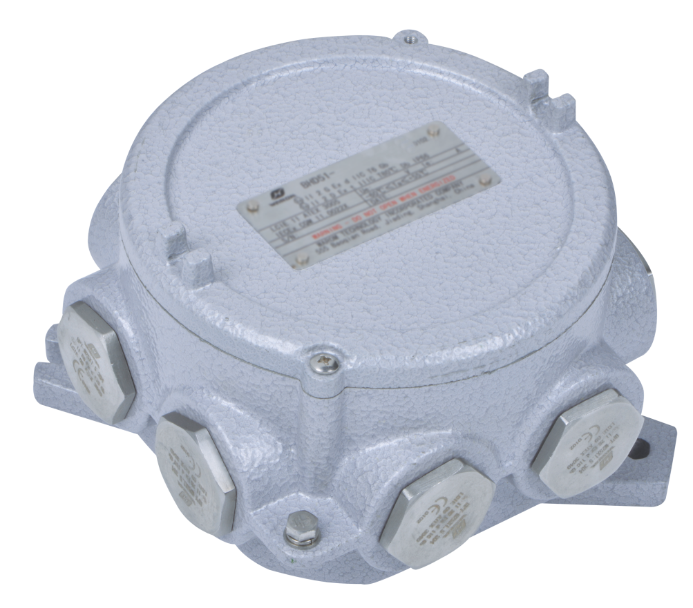
Ignition system power and control: The flare ignition panel itself is often located in a non-hazardous control room, but the high-energy igniter at the flare tip, the flame detection sensors, and the pilot gas solenoid valves are all within the hazardous envelope. This requires flameproof terminal boxes and junction boxes to transition from the main power cable to the individual device leads. BHD91 flameproof junction boxes with IIC certification handle this well, provided the cable entries are correctly specified for the armoured cable type used on site.
Lighting for access platforms and grade-level work areas: Flare stacks require periodic inspection, and access platforms need lighting that survives continuous outdoor exposure plus intermittent thermal radiation. Floodlight fittings designated BAT86 with IP66 protection and a -60°C to +60°C ambient rating cover most installations. For areas closer to the flare tip, where surface temperatures may exceed 55°C at the mounting point, we move to fittings with a verified higher ambient rating.
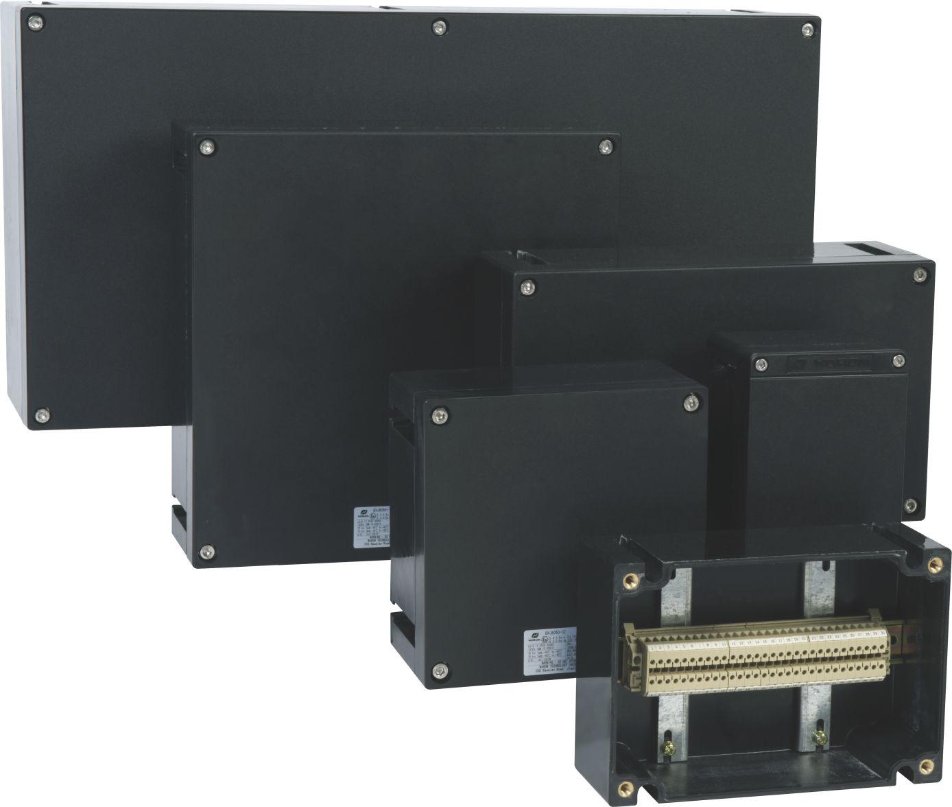
Cable management and distribution: The cable network from the main substation to the flare area equipment passes through multiple classified boundaries. Along the route, explosion-proof distribution boxes terminate incoming cables and branch out to individual loads. The BXM(D)8050 illumination distribution boxes, combining Ex d and Ex e construction, serve this function. At each transition point—from the main trench to the above-ground equipment rack, for example—the cable entry must maintain the explosion protection integrity, and the gland selection must match both the cable construction and the enclosure entry standard.
8050 Explosion-proof Illumination Distribution Boxes)
Instrumentation connections: Vent headers and flare knockout drums require level instrumentation, pressure transmitters, and temperature probes. The connection between the field instrument and the home-run cable typically passes through a terminal box. BXJ8050 increased safety terminal boxes provide centralized connection points and simplify maintenance access. For offshore or coastal flare installations, where salt spray adds corrosion to the thermal load, stainless steel enclosures become a practical necessity—the BXJ-S terminal boxes in 316 stainless steel address this requirement.
Cable gland selection: This deserves separate attention because it is the component most often underspecified. For flare system installations where cable runs are exposed to above-ambient temperatures, I recommend nickel-plated brass DQM-III flameproof glands for all Zone 1 entries. The nickel plating resists corrosion, and the flameproof barrier construction handles the thermal expansion differences between the brass body and the steel wire armour without compromising the flame path.
What Certification Standards Govern Flare System Electrical Equipment?
For international projects, the certification landscape has consolidated around three frameworks: IECEx, ATEX, and, for installations under U.S. influence, the NEC system with UL listing.
IECEx certification under the IEC 60079 series provides a globally recognized baseline. Equipment carries an IECEx Certificate of Conformity issued by an accepted certification body. For flare system equipment, the relevant parts of IEC 60079 include Part 0 (general requirements), Part 1 (flameproof Ex d), Part 7 (increased safety Ex e), and Part 31 (dust ignition protection, relevant for solid particulate near the flare if coke or carbon dust accumulates).
ATEX certification under the European Directive 2014/34/EU is mandatory for equipment placed on the market in the EU. The ATEX marking on a junction box or cable gland gives you the equipment group (II for surface industries), the category (2G for Zone 1 use), and the protection concept. A typical ATEX marking for flare area equipment reads “II 2 G Ex db IIC T4 Gb.” That tells you it is suitable for Zone 1, flameproof, IIC gas group, T4 temperature class, with a high level of protection.
For projects in China, CNEX certification applies, following GB/T 3836 standards that align closely with IEC 60079. The certification process requires submission of design documents, type testing at an accredited laboratory, and factory inspection.
A point I emphasize to project teams: never accept a certificate without verifying the certificate number against the issuing body’s online database. We have seen cases where certificates are genuine but have been suspended, or the production site listed on the certificate differs from the actual manufacturing location. A five-minute database check prevents a project delay twelve months later during commissioning.
How to Evaluate Suppliers for Flare System Explosion Proof Equipment
When your project includes flare system equipment, the supplier’s technical capability matters more than their catalog breadth. Here is what we examine when qualifying a new source.
First, verify that the manufacturer holds valid, current certificates from at least two recognized certification bodies. For global projects, an IECEx certificate from a body such as TÜV, LCIE, or SGS combined with an ATEX certificate from an EU-notified body provides cross-recognition in most jurisdictions.
Second, examine the product range for completeness. A flare system requires multiple equipment types—junction boxes, terminal boxes, distribution panels, cable glands, lighting, and possibly control stations. If the supplier manufactures all of these in-house, the compatibility between enclosures and cable entries is already validated. When you mix enclosure Brand A with gland Brand B, you assume responsibility for verifying that the combined assembly maintains the explosion protection.
Third, request factory acceptance test documentation for similar projects. The FAT reports should show routine tests—verification of flame path dimensions, enclosure pressure testing, dielectric strength testing, and earth continuity measurement—as well as certificate-specific type test data. For the Tilenga project in Uganda, our FAT documentation covered every enclosure shipped, with serial-number traceability back to the raw material heat number.
Lead times deserve realistic expectations. Custom-configured distribution cabinets built to a specific single-line diagram and cable schedule typically require twelve to sixteen weeks from approved drawings to shipment. Standard catalog products can ship from stock in two to four weeks, depending on the configuration. Plan your procurement schedule so that the long-lead items—the main distribution panels—are ordered first, with standard junction boxes and cable glands following.
For projects in regions with extreme ambient conditions, confirm that the manufacturer has tested beyond the standard temperature range. Equipment rated for -40°C to +60°C ambient covers most installations, but if your flare system is in a desert location where solar radiation adds 15°C to the enclosure surface temperature before the flare even lights, you need to discuss this with the supplier’s engineering team, not the sales desk.
Common Questions About Flare System Explosion Proof Equipment
What temperature class do I need for equipment near a flare stack?
Lead with a direct answer: T4 (135°C maximum surface temperature) is the minimum I recommend, even when the gas present would allow T3 (200°C). The temperature class is about the equipment’s own surface temperature under rated conditions, and when the surrounding air is already warmer from flare radiation, the margin between operating temperature and the T-class limit shrinks. If your flare gas contains carbon disulfide or other low-ignition-temperature compounds, you may need T5 or T6 regardless. When in doubt, run a thermal study that accounts for both ambient solar radiation and flare radiation at the equipment mounting location before locking the specification.
Can I use the same cable glands for Zone 1 and Zone 2 flare areas?
Within the same gas group and cable type, yes, but with a caveat. A DQM-III flameproof gland certified for IIC covers both Zone 1 and Zone 2. The difference is in the installation practice: Zone 1 demands a flameproof entry with a verified flame path, while Zone 2 permits increased safety entries under certain conditions. However, in flare areas, I prefer flameproof glands throughout because the thermal cycling can degrade an increased safety gland’s seal over time, and the consequence of a degraded seal near a continuous ignition source is not one you want to discover during an audit. If your vent header area is cooler and thermally stable, Ex e glands with a properly selected sealing ring perform reliably.
What documentation should I request from the supplier before shipment?
At minimum, request: (1) valid IECEx or ATEX certificate for each product type, with the certificate number clearly stated on the order confirmation, (2) a declaration of conformity signed by an authorized representative, (3) the factory acceptance test report including dielectric, earth continuity, and enclosure pressure test results for each item, and (4) installation and maintenance instructions in the project language. If the equipment is destined for a project that requires classification society approval—common for offshore flare installations—request the design appraisal document or type approval certificate from the relevant society. For any supplier who hesitates to provide these documents before shipment, I recommend finding a different supplier before the purchase order is signed.
Does an IP66 rating mean the enclosure is suitable for outdoor flare area use?
IP66 confirms protection against powerful water jets and dust ingress, which is a baseline requirement for outdoor hazardous area equipment. What it does not address is the temperature at the sealing surfaces, the UV resistance of the gasket material, or the corrosion resistance of the enclosure fasteners after years of exposure. For flare area outdoor use, the enclosure material, surface treatment, and ambient temperature rating are the critical parameters alongside the IP rating. Aluminum enclosures with a powder-coated surface and stainless steel fasteners hold up well; standard painted steel enclosures do not. Share your environmental conditions—not just the zone and gas group—when requesting a quotation, and ask the supplier to confirm the enclosure material and surface treatment in writing.
If you’re interested, check out these related articles:
Love And Respect For The Elderly, Warm Sunset Red
WAROM “INNOVATION” Unveils a New Era of Precision Medicine
Warom at SMM Hamburg
WAROM at IEW 2025
With over a decade of experience, he is a seasoned Explosion-Proof Electrical Engineer specializing in the design and manufacture of safety and explosion-proof products. He possesses in-depth expertise across key areas including explosion-proof systems, nuclear power lighting, marine safety, fire protection, and intelligent control systems. At Warom Technology Incorporated Company, he holds dual leadership roles as Deputy Chief Engineer for International Business and Head of the International R&D Department, where he oversees R&D initiatives and ensures the precise delivery of design documentation for international projects. Committed to advancing global industrial safety, he focuses on translating complex technologies into practical solutions, helping clients implement safer, smarter, and more reliable control systems worldwide.
Qi Lingyi