

Explosion proof motor control centers for hazardous area pumps rarely fail because the contactor is undersized. They fail because the motor data sheet, the hazardous area certificate, and the cable entry drawing were never reconciled before the order was placed. I have reviewed pump skid packages across oil, gas, and chemical projects where a sound enclosure arrived with the wrong overload range, or where the correct starter could not accept the armored cable specified for a Zone 1 location. The practical fix is to treat the MCC as one integrated hazardous area assembly from the first data sheet review, not as a group of certified components bolted together during site installation. That changes what belongs in the quotation and what gets checked before release.
Hazardous Area Pump MCCs Require More Than a Certified Enclosure
A pump drive is only one part of a hazardous area control loop. The motor control center may be mounted in a nonhazardous electrical room feeding a motor in Zone 1, or it may sit on the skid inside its own Ex d or Ex e enclosure. The location changes the enclosure requirement and the acceptable components. In most plant designs, the MCC is kept in a safe area and the motor circuit uses flameproof or increased safety terminations at the pump. When the MCC must be local, the enclosure must match the gas group, temperature class, and zone of the skid, not just the motor nameplate.
The distinction matters before any quotation. A panel built for an electrical room does not become a hazardous area panel because the motor is in Zone 1. The field connection, the cable glands, and the starter enclosure each have to meet the same classification logic. If only the motor is considered, the buyer receives a panel that looks correct on the drawing and creates a compliance problem during inspection.
Zone and Division Ratings Decide the Enclosure and Components
The protection method changes more than the enclosure material. A Zone 1 pump may require Ex d motor starters or Ex e terminals inside a flamepath housing. A Zone 2 pump often permits Ex nA, Ex ec, or restricted breathing components, but that does not mean any industrial panel can be placed there. When a buyer sends only the phrase “explosion proof MCC” without the zone, the supplier must either quote the worst case or delay the quote with questions.
| Area classification | Typical pump MCC protection approach | Detail to verify |
|---|---|---|
| Zone 1, gas group IIC | Ex d flameproof enclosure or Ex e compartment with flameproof components | Pressure piling and tight machined flamepaths |
| Zone 1, gas group IIB | Ex d or Ex e enclosure rated for IIB | Avoid paying for IIC if the gas does not require it |
| Zone 2, gas group IIC or IIB | Ex nA, Ex ec, or restricted breathing components in a certified enclosure | Confirm every arcing component is protected or absent |
| Class I Division 1 | Explosionproof enclosure with listed motor starters | Confirm the NEC listing matches the class and group |
| Class I Division 2 | Nonincendive circuits, sealed contacts, or explosionproof enclosure | Confirm the panel is not treated as ordinary industrial equipment |
The same gas group and temperature class logic that limits a pump MCC also carries into field devices on the same skid. <Explosion-Proof Solenoid Valves: Gas Pipeline Control Safety covers how control circuits around gas pipelines are evaluated so the protection concept stays consistent from the starter to the final element.
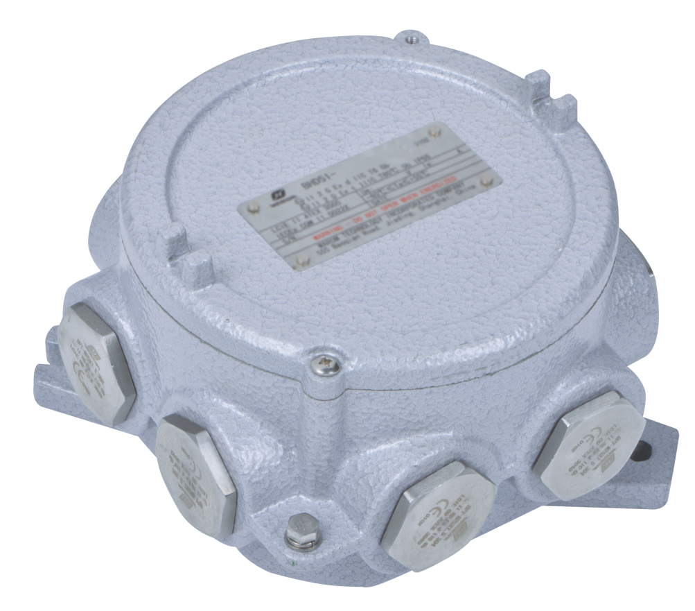
A site with hydrogen or acetylene can move a pump set from gas group IIB to IIC, and that changes the enclosure construction. Temperature class also limits the contactor and overload relay combination because the surface temperature of the components inside the enclosure must stay below the gas ignition temperature. These details cannot be resolved after the panel is built.
Motor Data Sheet Details Change the Explosion Proof Pump MCC Selection
A starter cannot be selected from horsepower alone. The locked rotor current, service factor, starting method, and duty cycle all decide overload settings and contactor size. If the pump is a high inertia crude oil transfer pump with a long acceleration time, a standard Class 10 overload curve may trip during start. Class 20 or Class 30 may be required. If the starter has a VFD bypass, the contactor must be rated for the bypass current and the enclosure temperature rise must be checked at the specified ambient. Missing one of these values changes the quote and often the enclosure size.
If your application includes a long acceleration duty, a VFD bypass, or a motor above 100 kW, it is worth confirming the overload class and bypass contactor rating before the design is frozen. Send the motor data sheet and starting curve to gm*@***om.com and we can check the MCC configuration against the pump duty instead of quoting from horsepower alone.
A similar mismatch appears in chemical plant projects when the MCC is ordered before the hazardous area schedule is final. In the General Paint electrical safety upgrade in Mexico, the practical value came from walking the site first, identifying flammable gas and dust risks, and then building the electrical package around the actual classification. The same principle applies to pump control: the zone drives the design, not the other way around.
Cable Entries and Earthing Are Where Explosion Proof MCC Approvals Stall
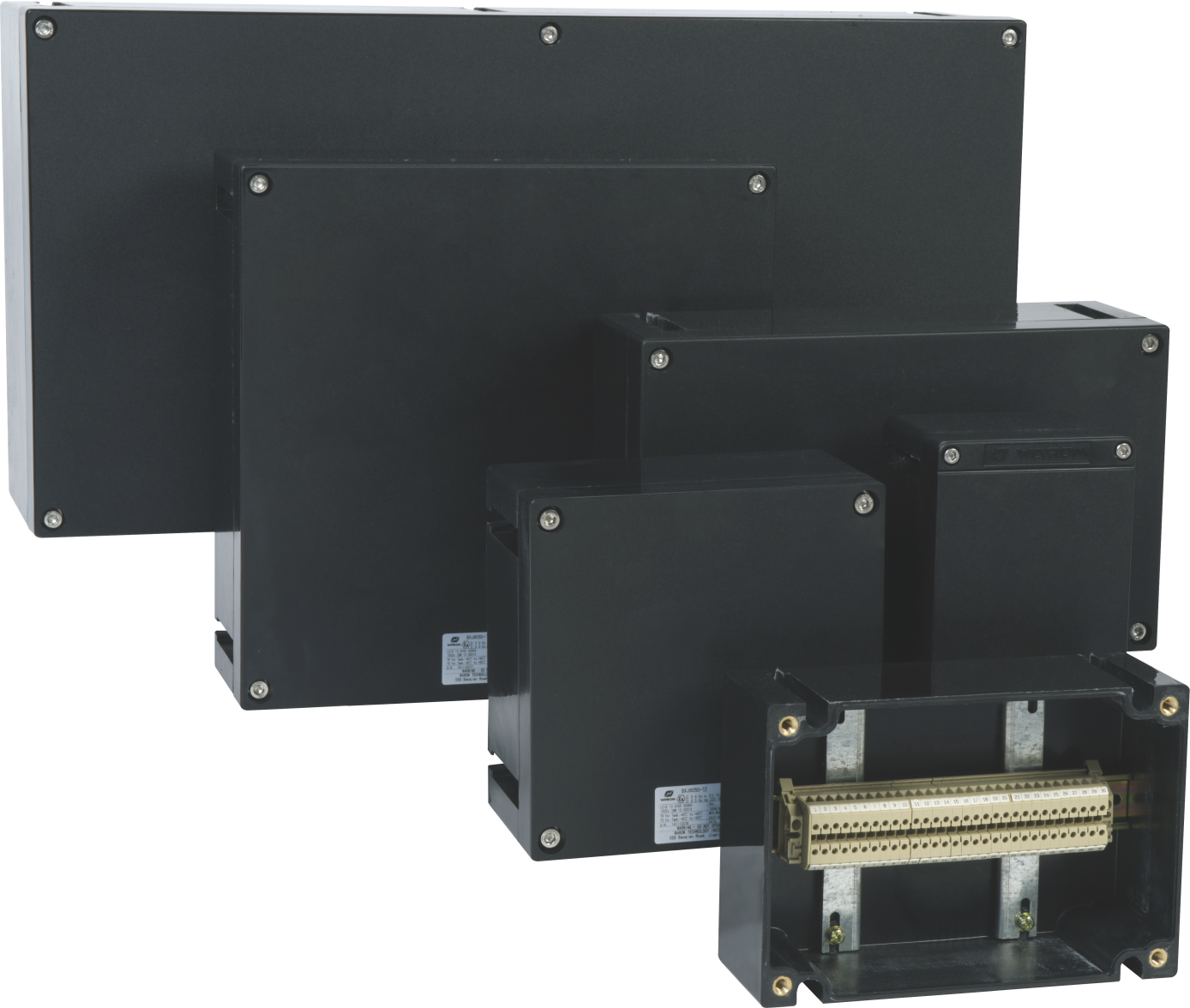
Cable entry is where most approvals stall. An explosion proof motor control center may be certified as an enclosure, but the installed assembly must also meet the cable gland and blanking element requirements. A DQM-III Ex d gland may be correct for armored cable in one entry, while a different entry needs an Ex e gland for an unarmored instrument cable. If the supplier does not know the cable schedule, it cannot drill the entries correctly. Once the enclosure leaves the factory, modifying a flameproof entry on site is exactly the kind of change that can void the certification.
Internal and external earthing terminals, bonding conductors, and the earth path through gland plates are not cosmetic details. For outdoor pump skids in coastal or high vibration locations, IP66 and corrosion class WF2 are normal minimums. Stainless steel fasteners and anti-loosening treatment matter more when the equipment is exposed to salt spray and constant vibration.
A Supplier Should Quote From the Motor List, Not the Panel Alone
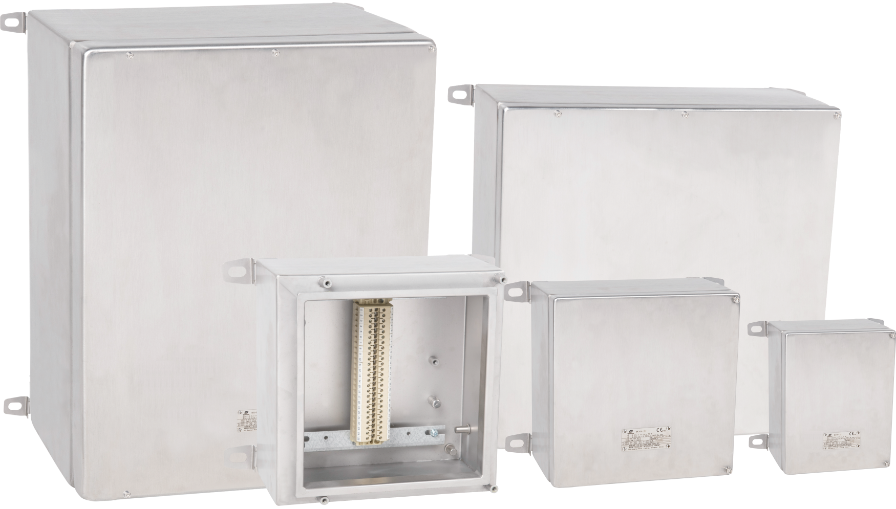
The risk is not that a supplier cannot build a hazardous area panel. The risk is that the quotation arrives before the right questions have been asked. At Warom, we prefer to start from the motor list, pump starting method, hazardous area schedule, and cable schedule together. That way we confirm enclosure protection type, overload class, cable entry sizes, temperature class, and certification route before the design is released.
Send your pump data sheet, area classification drawing, and cable schedule to gm*@***om.com or call +86 21 39977076 or +86 21 39972657 and ask for a technical review rather than a price only. A purchase order should start from a configuration that can pass the site inspection.
Buyers Ask These Questions Before Ordering a Pump MCC
What is the difference between an explosion proof MCC and a standard industrial MCC?
The enclosure and every current-carrying component are selected so that an internal arc, spark, or hot surface stays isolated from the flammable atmosphere outside. A standard industrial panel is built for a safe area and has no tested flamepath, no certified cable glands, and no temperature class rating for flammable gas. The difference is not limited to wall thickness. It includes the certification trail, the component selection, the earthing design, and the restrictions on site modification.
When can I use a standard panel for a Zone 2 pump instead of an explosion proof MCC?
It depends on the gas group, the zone, and whether the panel contains components that arc or produce heat in normal operation. Zone 2 does permit some non-sparking Ex nA or Ex ec designs, but ordinary industrial contactors can still create arcs during switching. If the panel contains relays, contactors, or VFD components that are not certified for the zone, a standard industrial panel is not acceptable. The practical test is whether every component inside can be matched to an IEC 60079 protection concept.
Many buyers assume every hazardous area pump starter must be flameproof, is that true?
That assumption adds cost without always adding protection. Flameproof Ex d construction is one valid method, especially for Zone 1 and gas group IIC. Increased safety Ex e is also used where the components do not produce arcs in normal operation, and Zone 2 may allow less expensive restricted breathing or non-sparking methods. The right method depends on the zone, gas group, starting method, and whether arcing components are present inside the enclosure.
What documentation should I request before accepting an explosion proof motor control center?
Request the drawing that matches the actual cable entries, the certificate for the enclosure, and the component certificates for the devices installed inside. The test certificate only has value if the exact cable entry positions, gland types, temperature class, and component layout match the delivered panel. Also check that the earthing arrangement and any field-mounted control station are shown on the same assembly drawing. Share your motor list and hazardous area schedule and we will confirm the certificate package and entry drawings before shipment.
If you’re interested, check out these related articles:
OGI 2024 Jakarta is underway
Explosion Proof Lighting for Grain Silos and Flour Mills: Safety Compliance
The 2025 International Industrial Explosion-Proof Technology Forum was successfully held in Shanghai
With over a decade of experience, he is a seasoned Explosion-Proof Electrical Engineer specializing in the design and manufacture of safety and explosion-proof products. He possesses in-depth expertise across key areas including explosion-proof systems, nuclear power lighting, marine safety, fire protection, and intelligent control systems. At Warom Technology Incorporated Company, he holds dual leadership roles as Deputy Chief Engineer for International Business and Head of the International R&D Department, where he oversees R&D initiatives and ensures the precise delivery of design documentation for international projects. Committed to advancing global industrial safety, he focuses on translating complex technologies into practical solutions, helping clients implement safer, smarter, and more reliable control systems worldwide.

Qi Lingyi