

ATEX fire and gas detection systems identify a developing fire or flammable gas release before it reaches a hazardous condition, and they initiate the alarm, ventilation, shutdown, or isolation action required for that site. A compliant system is not a collection of certified detectors mounted in the right place; it is a coordinated loop of field devices, wiring accessories, control logic, alarm devices, and documented verification. For buyers, the main task is to define the hazard scenario and certification data before selecting individual equipment.
What ATEX Fire and Gas Detection Systems Must Do
ATEX certification confirms that a device can be installed in a classified atmosphere without becoming an ignition source. A fire and gas detector must also perform its detection function reliably. Under the ATEX Equipment Directive, equipment intended for use in potentially explosive atmospheres is assessed for normal operation and foreseeable faults [1]. In practice, that means the detector enclosure, cable entry, alarm beacon, and associated wiring accessories all need a valid ATEX classification for the declared zone, gas group, and temperature class.
Detector Types for Different Fire and Gas Risks
Selection starts with the release scenario. A gas cloud, an open fire, a smoldering cable, and a pressurized leak present different signals, and no single detector class covers all of them. The table below separates common ATEX detection technologies by the hazard they are best suited to identify and by the limits that affect field performance.
| Detector type | Best-fit hazard | Main limitation |
|---|---|---|
| Point infrared flame detector | Open hydrocarbon fire | Needs line of sight to the flame; may false alarm from arc radiation |
| Catalytic bead gas detector | Flammable gas in ambient air, measured against the lower explosive limit | Needs oxygen; catalyst can be poisoned |
| Infrared gas detector | Hydrocarbon gas, oxygen-poor or sulfur-heavy areas | Most are not suitable for hydrogen |
| Electrochemical cell | Hydrogen sulfide, carbon monoxide, and oxygen depletion | Limited sensor life and temperature range |
| Open-path infrared gas detector | Perimeter leak detection | Fog, rain, or lens fouling can reduce signal |
| Ultrasonic gas detector | High-pressure gas leaks | May miss low-pressure or accumulated gas |
Flame, Smoke, and Heat Detection
Flame detectors respond quickly to an open hydrocarbon fire, but they require a clear line of sight to the flame. Smoke detection is slower for a flame-producing leak and is more useful for incipient cable, insulation, or smoldering failures. Heat detection is less selective but can cover congested areas where optical detectors cannot see the event.
Combustible Gas Detection
For flammable gas releases, catalytic bead sensors measure concentration relative to the lower explosive limit, while infrared sensors avoid catalyst poisoning and work in oxygen-poor or sulfur-heavy environments. Catalytic sensors need oxygen and can lose sensitivity after exposure to silicones or halogenated compounds. Most infrared gas detectors are not suitable for hydrogen, so the site gas list must be confirmed before selecting a technology.
Toxic and Oxygen Detection
Electrochemical cells measure toxic gases such as hydrogen sulfide and carbon monoxide, and they monitor oxygen depletion in occupied areas. They are primarily personnel-protection devices rather than explosion-prevention devices. A fixed fire and gas system often combines flammable gas, toxic gas, and flame channels in one control panel so a confirmed event can trigger both evacuation and process response.
ATEX Marking and Performance Requirements
The ATEX marking confirms that the device will not become an ignition source in the declared zone. It does not by itself confirm that the detector will respond correctly to the target gas. Detection performance is covered by application standards such as IEC 60079-29-1 for flammable gas detectors [2]. Buyers should request both the ATEX certificate and the performance data or calibration certificate.
A typical gas detector marking may read II 2 G Ex db ia IIC T6 Gb. This means Category 2 equipment for Zone 1, flameproof and intrinsically safe protection, suitability for Group IIC gases including hydrogen and acetylene, T6 surface temperature, and Gb equipment protection level. A device marked Ex d alone indicates a protection method, not the sensor technology, gas response, or lower explosive limit range required for the application.
Temperature class also matters when the detector is exposed to a hot process. T6 is the most restrictive and is suitable for gases with low ignition temperatures, but the detector must also be selected for ambient conditions and the expected process gas.
Designing a Detection System That Works in the Field
Detector location and the planned response action are part of the same safety function. A gas detector placed downwind of a flange may alarm too late if the release is on the other side of a congested module. Vapor density, ventilation, congestion, and leak direction all influence coverage. The detection layout should be based on the hazardous area classification and the site release study, not on a fixed spacing rule.
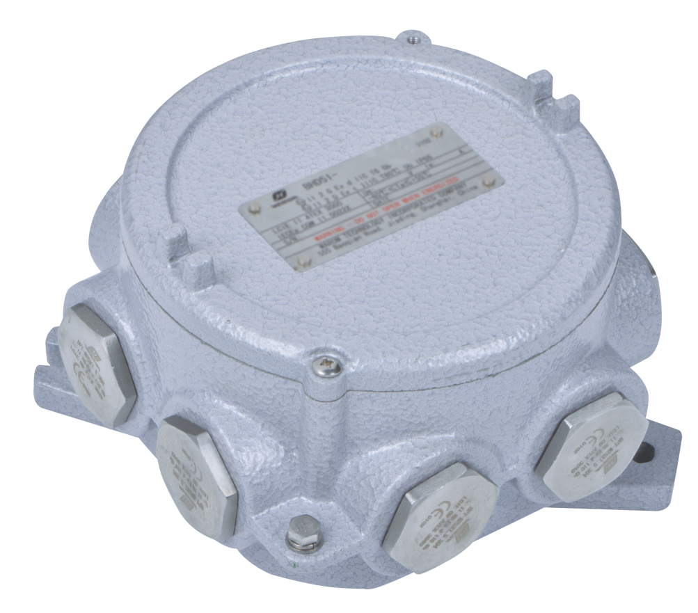
Field devices are only as reliable as the wiring that connects them. Every junction box, terminal, gland, and cable entry must be certified for the same zone and gas group, and the loop must retain the protection method declared by the certificate. A supplier package that combines certified detectors, junction boxes, and alarm devices with one documentation set reduces the inspection burden. Warom supplies certified junction boxes and terminal boxes for these circuits.
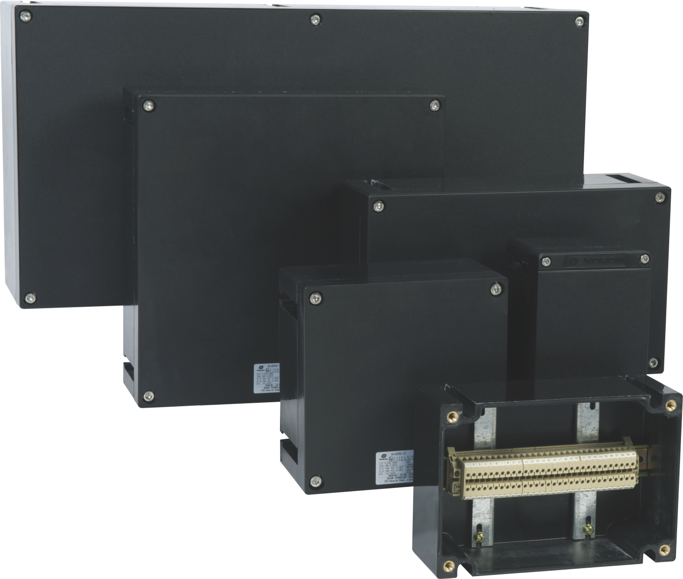
For multi-channel fire and gas panels, certified terminal boxes are commonly used to gather detector circuits before they enter the control package. The terminal arrangement should match the loop diagram and maintain the required separation between intrinsically safe and non-intrinsically safe wiring.
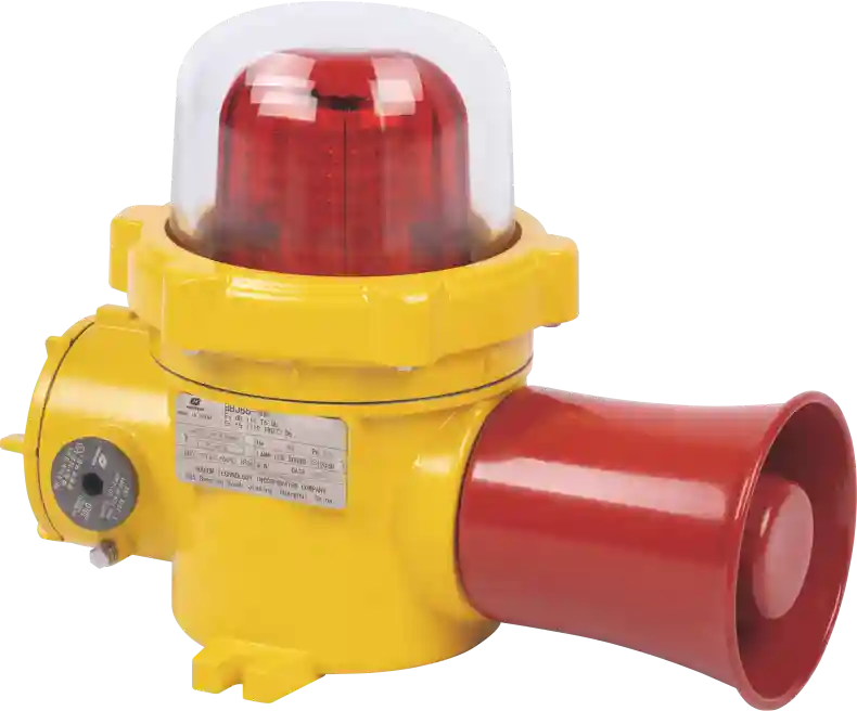
Alarm devices must also be certified for the same zone. A beacon or sounder placed where operators are present converts the detector signal into an immediate local warning before the central system acts.
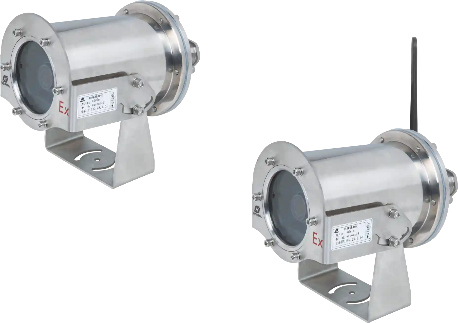
Where operators need visual confirmation before manual shutdown, an explosion-proof camera can be linked to the fire and gas system, but it does not replace a detector or a flame detector.
Voting logic should be defined before purchase. Where a site uses 2-out-of-N voting to reduce spurious trips while preserving safety, the detectors, inputs, and control outputs must be arranged to support that logic. The exact arrangement must match the risk study and operating philosophy.
On offshore and remote hydrocarbon facilities, the fire and gas system must also communicate with platform shutdown, ventilation, and alarm functions. If the loop only displays a gas reading but cannot execute a required isolation or alarm, the installation does not meet its stated safety intent.
Fire and gas loops on offshore installations need to be qualified together with the surrounding hazardous-area electrical equipment. <Explosion Proof Equipment: Offshore Drilling Hazardous Area Safety> covers the broader electrical safety package for drilling rigs and platforms.
Gas detection is the first step, but the dangerous release still needs to be isolated and ventilated. The detector output should land on a control action that closes the relevant isolation valve or starts the appropriate exhaust path, and that action must be tested during commissioning.
Fire and gas detection is only one part of the safety action chain. <Explosion-Proof Solenoid Valves: Gas Pipeline Control Safety> covers the isolation devices that must close when a gas detector reaches its trip point.
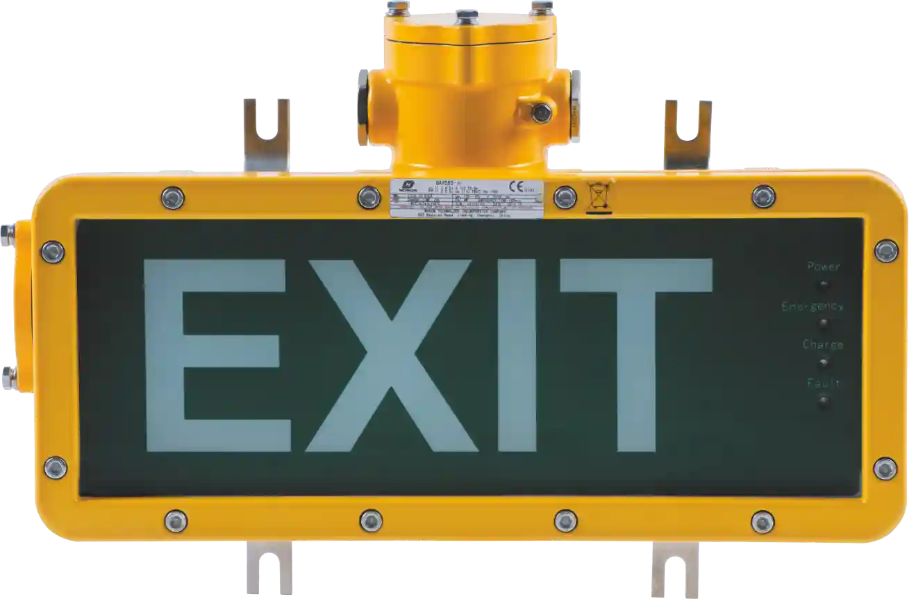
Alarm response must also cover the people in the area. Where a toxic or flammable gas alarm initiates evacuation, the emergency lighting and exit marking along the escape route need to remain available and suitable for the classified location.
Common Specification Mistakes That Delay Projects
Requests often ask for an ATEX detector without stating the zone, gas group, temperature class, target gas, alarm setpoint, or voting logic. The certificate then arrives and does not fit the actual hazard. Recurring issues include:
- No hazardous area classification or inconsistent Zone 1 and Zone 2 selection.
- Missing target gas list and lower explosive limit range.
- No alarm and trip setpoints for gas, flame, and toxic channels.
- No voting or shutdown action defined.
- Mixing ATEX zones with North American class and division language.
- Leaving cable glands, junction boxes, and terminals out of the package.
Acceptance Tests and Maintenance Checks
Before release, verify that the certificate matches the device nameplate and that the safety parameters match the loop design. A gas detector should be bump tested with the target gas and calibrated according to the manufacturer procedure. A successful bench test does not prove field response, because cable length, loop resistance, and installation conditions all affect the final measurement.
Inspection should also confirm gland continuity, earth continuity, alarm setpoints, and the control action to shutdown, isolation, or ventilation. Proof testing should simulate the full loop from sensor to alarm and to the final element, not only the detector output.
The certificate may include specific conditions of use, often marked X. Those conditions are part of the certification and must be reflected in the installation and operating instructions.
Plan Your ATEX Fire and Gas Detection Specification
Start with the site classification, target gas list, alarm setpoints, voting logic, environmental conditions, and the required certificate approvals. If you send these fields with cable entry and gland details, Warom can check whether the proposed detectors, junction boxes, terminals, and alarm devices form one compliant loop.
For project-specific review, contact Warom at gm*@***om.com or +86 21 39977076 / +86 21 39972657.
FAQ
Does an ATEX certificate cover gas detection performance?
No. The ATEX certificate confirms that the equipment is safe to install in the classified atmosphere, but it does not replace the detector performance standard. Request the ATEX certificate together with the IEC 60079-29-1 performance data, calibration certificate, and any alarm setpoint verification [2].
What is the difference between flame detection and gas detection?
Flame detection sees an established fire, while gas detection measures flammable gas before ignition. Many installations use both because a gas cloud can travel before reaching a detector, and flame detectors have line-of-sight limits.
Can Zone 1 approved equipment be installed in Zone 2?
Generally yes, when the equipment has an equal or higher category or equipment protection level and the gas group and temperature class cover the Zone 2 hazard. The certificate and installation instructions must still be checked because special conditions may restrict orientation, wiring, or accessories.
How often should fixed gas detectors be calibrated?
There is no single universal interval. The site follows the manufacturer minimum, local regulation, and the plant safety case. Detectors exposed to poisons, humidity, or frequent gas exposure often require more frequent bump tests, and any failed response check requires calibration or replacement before the detector is returned to service.
What should I include in an RFQ for an ATEX fire and gas system?
Include the hazardous area classification, target gas list, lower explosive limit range, alarm and trip setpoints, voting logic, detector technology preferences, certificate requirements, environmental data, cable entry details, and commissioning witness points. This gives the supplier enough information to propose a loop rather than a list of parts.
References
[1] European Parliament and Council, “Directive 2014/34/EU on the harmonisation of the laws of the Member States relating to equipment and protective systems intended for use in potentially explosive atmospheres,” Official Journal of the European Union, 2014.
[2] IEC, “Explosive atmospheres – Part 29-1: Gas detectors – Performance requirements of detectors for flammable gases,” IEC 60079-29-1.
If you’re interested, check out these related articles:
The foreign trade center mission building activities are colorful
Stainless Steel Explosion Protection for Marine Electrical Systems
CANTON FAIR 2023
Class 1 Division 1 vs Division 2 Lighting: 2025 Safety Guide
Balikpapan Industrial Expo – BEX
With over a decade of experience, he is a seasoned Explosion-Proof Electrical Engineer specializing in the design and manufacture of safety and explosion-proof products. He possesses in-depth expertise across key areas including explosion-proof systems, nuclear power lighting, marine safety, fire protection, and intelligent control systems. At Warom Technology Incorporated Company, he holds dual leadership roles as Deputy Chief Engineer for International Business and Head of the International R&D Department, where he oversees R&D initiatives and ensures the precise delivery of design documentation for international projects. Committed to advancing global industrial safety, he focuses on translating complex technologies into practical solutions, helping clients implement safer, smarter, and more reliable control systems worldwide.

Qi Lingyi