
Installing electrical monitoring on an offshore wind turbine isn’t the same as a factory or an onshore substation. Salt spray, constant vibration, and a deck that can shift under your feet change how every enclosure, connection, and sensor performs. Explosion proof monitoring systems for these sites must handle all of that while maintaining valid hazardous area certification, because the nacelle can accumulate flammable gas from batteries or transformer faults, and the confined space makes any ignition event far more serious than a fault on land. Most technical articles cover monitoring system features or communication protocols in isolation; what they rarely address is what we found repeatedly at Warom during project reviews: failures trace back not to hardware limits but to incomplete front-end engineering. The protection method, temperature class, and layout decisions made before procurement are what determine whether a system works for years or generates callouts from the first winter.
Where Explosion Proof Monitoring Is Required on an Offshore Wind Turbine
Offshore wind installations don’t have uniform hazardous area classifications across the entire structure. The most critical zones are inside the nacelle, near the transformer compartment, and within any enclosed space that contains or is adjacent to battery energy storage systems. Hydrogen outgassing from lead-acid or even some VRLA batteries under fault conditions can push a sealed nacelle into Zone 1 gas concentrations. Meanwhile, the tower base can become a Zone 2 area if cable entry sealing is compromised and gas rises from the monopile. We’ve seen project specifications that classified the entire nacelle as safe, only to have the authority require a full review after battery ventilation calculations showed otherwise. The lesson is straightforward: if your monitoring system components are only rated for non-hazardous areas, you are one battery fault away from an uncontained ignition risk.
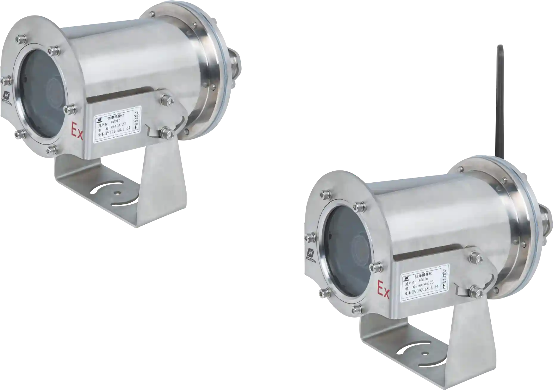
The monitoring system layout should map to the actual ventilation and gas dispersion analysis, not just a rectangle on an SLD. Ex d enclosures for cameras, pressure transmitters, and gas detectors are common. However, I’ve seen designs where the camera’s Ex d rating was fine but the mounting bracket allowed condensation ingress through an M20 entry that wasn’t sealed, creating a corrosion path within six months. The design must treat every penetration as part of the explosion proof integrity.
Gas Detection and Electrical Parameter Monitoring: What to Combine
A monitoring system that only reports gas %LEL or smoke alarm trips gives you a record of past events; it doesn’t help you prevent the next one. The offshore wind applications we’ve supported combine gas detection with electrical parameter monitoring on the same data backhaul. Specifically, we monitor transformer winding temperature, partial discharge signatures, and battery string voltage imbalance alongside gas readings. Why? Because a slowly rising battery cell temperature long before hydrogen concentration reaches 25% LEL can trigger an early maintenance intervention that avoids a full alarm. In one project, a client detected a failing battery string through voltage drift three weeks before gas detectors would have alarmed, because the monitoring logic was designed to correlate electrical anomalies with potential gas risks, not just trip on thresholds.
Partial discharge in a cast-resin transformer is another precursor. Moisture entering the enclosure through a breather drain that wasn’t specified for marine environments can degrade insulation, leading to partial discharge activity that is invisible to gas detection initially. If the monitoring system is only reading gas, that degradation goes unnoticed until the insulation fails and possibly ignites a hydrogen pocket. I’ve never seen a monitoring spec that didn’t include gas sensors; I’ve seen many that omitted electrical parameter monitoring, and the ones that had serious near-misses were always those.
| Gas Type | Typical Source | Detection Method | Alarm Threshold |
|---|---|---|---|
| Hydrogen (H₂) | Battery outgassing | Catalytic bead or electrochemical | 25% LEL (lower) standard, 15% LEL early warning common |
| Methane (CH₄) | Cable insulation decomposition under arc faults | Infrared or catalytic | 20% LEL |
| Carbon Monoxide (CO) | Overheated insulation / partial combustion | Electrochemical | 35 ppm TWA |
| Smoke / Aerosol | Insulation / component fire | Ionization or photoelectric | Pre-alarm at 0.5% obs/m |
Why Temperature Class T4 Is Often Wrong for Offshore Wind Electrical Compartments
Many monitoring system components are offered with T4 (135°C) temperature classification, and specifiers accept it because they assume the nacelle ambient will rarely exceed 40°C. That assumption often fails. A nacelle in constant summer sun, even on the North Sea, can reach internal ambient temperatures above 50°C when the turbine is not running at full speed and ventilation is reduced. Inside a junction box or control panel that contains a power supply and a network switch, the internal hotspot can exceed 120°C. With a T4 classification and 50°C ambient, the allowable enclosure internal rise is only about 85°C, which is often insufficient. I’ve recommended T5 (100°C) for junction boxes and T6 (85°C) for cable glands and connection heads inside nacelle compartments that are directly adjacent to transformer enclosures, because the transmitted heat from the transformer pushes the local ambient above what the external air temperature suggests. Upgrading from T4 to T5 is a small cost compared to replacing a burned-out control panel that lost its Ex certification after thermal degradation.
The same applies to gas detector sensor heads. A catalytic bead sensor that is T4 rated and operated near its maximum ambient for a year will drift, and the calibration frequency required to maintain it often gets ignored offshore until the next statutory inspection, leaving a gap. A T5 or T6 sensor head with separate, lower-temperature signal conditioning electronics in a different enclosure is a more reliable arrangement.
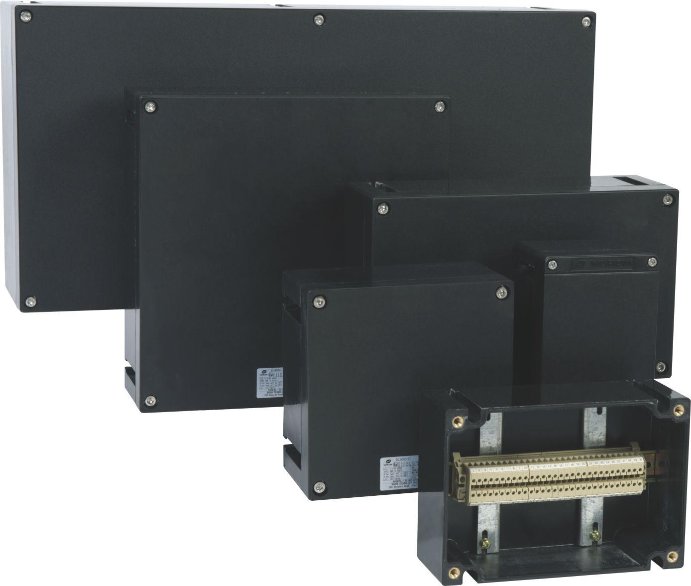
Enclosure Material and Cable Entry Design: The Monitoring System’s Weakest Link
The best gas detectors and PTZ cameras can’t function if their enclosure corrodes or the cable gland loses its IP seal. For offshore wind, I specify stainless steel 316L for all enclosures that house monitoring electronics, not because aluminium alloy is inadequate, but because the combination of salt mist and inevitable minor scratches in the paint coating of aluminium leads to filiform corrosion that can bridge flamepaths. The Ex d flamepath on a corroded enclosure no longer meets the standards, even if the device still powers on. We’ve seen enclosures fail inspection after two years because the original spec used aluminium with a polyester powder coat that wasn’t thick enough for offshore conditions. GRP enclosures are acceptable for junction boxes in some areas but can suffer from microcracking if subjected to constant vibration; for a monitoring system that includes a camera with moving parts (pan/tilt), metal is preferred.
Cable entry design is equally critical. Armored cable with a nickel-plated brass Ex d gland and a deluge boot is our baseline. For fiber optic cables that carry camera video back to the control room, a breather drain in the vertical cable run prevents condensation inside the gland itself. I’ve learned to specify that the gland must be installed with the cable entry facing downward, and the total length of the unarmored section inside the enclosure must be less than 150 mm to avoid a situation where the cable insulation, softened by heat, sags and opens a direct path into the enclosure.
Monitoring System Integration and Remote Communication: What to Ask the Supplier
When we supply a monitoring system for an offshore wind project, the client usually asks: “Does it support Modbus TCP? Can I feed the data into my SCADA with OPC UA?” The answer should go beyond protocol compatibility. The real question is: does the explosion proof monitoring system contain a data concentrator that can prioritize alarm signals even when the network is congested, and can it timestamp events with IEC 61850-compliant timestamps so that the sequence of a partial discharge alarm, a gas alarm, and a circuit trip can be reconstructed precisely after an incident? A simple black-box recorder that transmits every Modbus register every five seconds is not enough. I’ve designed systems where the monitoring sub-panel, housed in a pressurized Ex p cabinet in the tower base, runs an embedded Linux controller with local storage for 30 days of trend data. That way, if the fiber link drops during a storm, the turbine remains monitored locally and the data is backfilled when the link recovers.
Remote configuration also matters. Offshore access is slow and expensive. A monitoring system that requires physical disconnection of sensors for calibration or configuration changes costs the operator thousands in crew transfer expenses. That’s why the systems we deliver include remote sensor zero and span calibration through the HART protocol from the onshore control center, and the camera’s presets and cleaning cycle can be triggered remotely. When I write a spec, I require that all calibration and diagnostic functions exposed on the local HMI are also accessible via the network interface, without requiring a separate software license.
Monitoring System Testing and FAT: What We Verify Before Shipment
We perform a factory acceptance test (FAT) for every monitoring system before it leaves our workshop, but for offshore wind I add tests that go beyond the standard IEC 60079 checks. Specifically, we test the entire assembled system, including interconnecting cables and glands, under a thermal cycle from -20°C to +60°C while monitoring for any communication dropouts. Cold start at -20°C with a 12-hour soak is mandatory because the turbine can be shut down in winter and then started remotely, and if a camera’s pan motor doesn’t wake up, the crew has to wait for a weather window to visit. We also perform a condensation test: the system is placed in a chamber at 40°C and 95% relative humidity for 48 hours, then the temperature is ramped down to -5°C over 4 hours while operating at full load. Any internal condensation that forms in the camera housing or the control panel will show up as fogging on the lens or as a low insulation resistance reading; either fails the FAT. This test isn’t mandated by Ex standards, but it has saved more than one project from a winter startup problem.
We also verify that the Ex d flamepath gap on all enclosure covers and inspection windows is within tolerance using a feeler gauge after the thermal cycle, because differential expansion of the enclosure and the bolted cover can alter the gap if the bolting scheme wasn’t designed to maintain compression over a wide temperature range. For offshore wind, where the temperature swing can easily be 30°C between day and night and 50°C seasonally, this check is not optional.
The Cost Structure of Explosion Proof Monitoring for Offshore Wind: What Actually Drives the Price
When a project manager sees a quotation for an explosion proof monitoring system for an offshore wind turbine, the biggest number is often the enclosure material and the certification documentation, not the electronics. Stainless steel 316L enclosures can be 2 to 3 times the cost of aluminium alloy, but as I’ve explained, the maintenance cost difference over 10 years makes stainless the better choice. The certificates are another driver: every monitoring component must carry an IECEx or ATEX certificate that lists the exact gas group (IIC), temperature class, IP rating, and ambient temperature range applicable to the offshore wind installation. If the certificate shows a temperature range only up to +40°C, and the project requires +50°C, the component cannot be used, or a supplementary test report must be obtained from the manufacturer. That paperwork costs money and lead time.
Integrated FAT and marine-specific documentation such as a Declaration of Conformity for the Marine Equipment Directive (MED) for certain components also add cost but are often unavoidable for European offshore projects. I advise clients or project planners to budget for these compliance costs up front. It’s far cheaper to specify the correct materials and testing during the FEED stage than to discover during commissioning that the installed equipment doesn’t meet the marine requirements and must be replaced under a variation order. When you send your specification to Warom (gm*@***om.com or call +86 21 39977076) with details like required certificates, cable types, and environmental conditions, I can provide a cost breakdown that separates mandatory compliance items from optional features, so you can decide where to allocate budget without surprises later.
Common Questions About Explosion Proof Monitoring Systems for Offshore Wind Electrical Systems
Are intrinsically safe (Ex i) monitoring systems a better choice than Ex d for offshore wind?
Not for the entire system. Ex i is excellent for sensor heads in Zone 0 or Zone 1 where continuous exposure to gas is possible and the device must remain safe even during a fault. However, for cameras, data concentrators, and power supplies, Ex i is not practical due to power limitations. We often use a hybrid: gas detectors and vibration sensors on Ex i circuits, and ex d enclosures for the main monitoring electronics. The key is ensuring that the Ex i circuits are isolated from the higher-power circuits with certified barriers and that the cabling separation meets IEC 60079-14 requirements.
What maintenance interval should I plan for an explosion proof monitoring system on a wind turbine?
I recommend a 12-month physical inspection of all enclosures, glands, and sensors, even if the system reports no faults. The inspection should include a visual check of the flamepath surfaces for corrosion, measurement of the IP gasket compression, and a torque check of all gland locknuts. Gas detectors that use catalytic bead sensors should have a bump test with calibration gas at least every 6 months, and a full calibration at 12 months. If the site is remote, I specify electrochemical sensors with a longer calibration interval and automatic diagnostic checks that can be run remotely each month.
How do I handle the monitoring system when the turbine is in a non-hazardous area classification overall?
Even if the turbine’s official hazardous area drawing shows only a small Zone 2 around the battery cabinet, I still classify the monitoring equipment in the immediate vicinity of that cabinet as Zone 2, and I use at least Ex nA or Ex ec equipment. That provides an additional layer of protection without the full cost of Ex d. However, if the battery cabinet ventilation is not fully independent of the nacelle ventilation, I treat the nacelle as Zone 2. Too many projects have been caught out by proving the area is safe only under ideal conditions, ignoring maintenance scenarios where ventilation is off. If your classification is uncertain, share your existing area drawings and battery specifications at gm*@***om.com and I can recommend a monitoring layout that’s both compliant and cost-effective.
If you’re interested, check out these related articles:
Zone 21 Dust Hazards: Essential Explosion Proof Electrical Equipment
Explosion Proof Lighting for Grain Silos and Flour Mills: Safety Compliance
Ultimate Guide to Portable Explosion Proof Lighting
With over a decade of experience, he is a seasoned Explosion-Proof Electrical Engineer specializing in the design and manufacture of safety and explosion-proof products. He possesses in-depth expertise across key areas including explosion-proof systems, nuclear power lighting, marine safety, fire protection, and intelligent control systems. At Warom Technology Incorporated Company, he holds dual leadership roles as Deputy Chief Engineer for International Business and Head of the International R&D Department, where he oversees R&D initiatives and ensures the precise delivery of design documentation for international projects. Committed to advancing global industrial safety, he focuses on translating complex technologies into practical solutions, helping clients implement safer, smarter, and more reliable control systems worldwide.
Qi Lingyi