

Explosion proof cable glands are the smallest items on a Zone 1 bill of materials and the ones most often chosen by thread size alone. In an ATEX installation that choice decides whether a flameproof enclosure, junction box or control station keeps the protection concept it was certified with. Zone 1 describes an area where an explosive gas atmosphere is likely to occur during normal operation occasionally [1]. The enclosure certificate covers the box. The cable entry device covers the opening, and it carries its own certificate. Specify the gland from the equipment certificate and the cable construction first, then confirm the thread.
What an Explosion Proof Cable Gland Does in a Zone 1 Enclosure
A Zone 1 gland has three duties that are tested separately. It holds the cable against a defined pull force, it keeps moisture and dust out at the stated IP rating, and on a flameproof enclosure it closes a flame path. The first two are mechanical and sealing duties. The third is a protection duty, and it is the reason a gland on an Ex d box has to be a certified cable entry device rather than a general-purpose accessory [3].
Equipment installed in Zone 1 carries EPL Gb, which corresponds to category 2G under the ATEX directive [2]. An enclosure certified to that level is certified as a system: body, cover, entries and plugs together. A four-entry junction box with two cables in service needs two certified glands and two certified blanking plugs. Fit an uncertified gland in the third hole and the fourth hole is not the only thing that has changed. The protection concept is no longer the one that was examined.
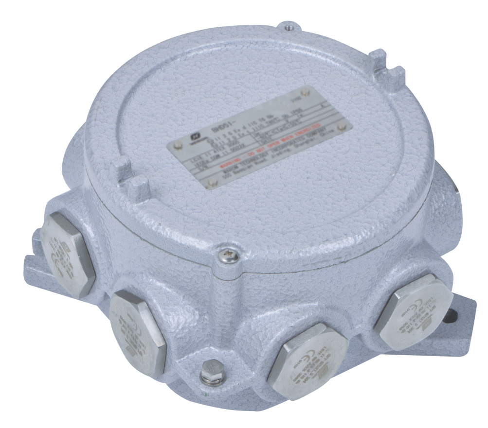
The flame path is the part buyers rarely see. In a flameproof gland, the joint between gland body and enclosure, the seal around the cable and, where a barrier is used, the compound around the cores all sit between an internal ignition and the surrounding atmosphere. Gas travelling along the interstices of a braided or stranded cable can bypass the enclosure flame path entirely, which is why cables without a gas-tight construction are the usual reason a sealing gland is specified.
A fourth duty is often left to the installer. The armour or braid clamps into the gland and must be bonded to the enclosure earth. A gland that holds the cable correctly but leaves the armour unbonded has done only part of its work.
Reading the ATEX Marking on an Explosion Proof Cable Gland
A marking string for a Zone 1 gland typically reads CE, a four-digit notified body number, II 2 G, Ex db IIC Gb, the certificate number, the ambient range, the thread size and the IP code. Each field answers a different question.
- II is equipment group II, surface industry rather than mining.
- 2 is category 2, the level that permits Zone 1 use.
- G states a gas atmosphere rather than dust.
- db is flameproof protection with EPL b.
- IIC covers the gases that include hydrogen, and equipment rated IIC may be used where IIB or IIA is required.
- Gb is the equipment protection level itself.
An X after the certificate number is not a variant code. It means specific conditions of use, which are listed in the certificate schedule, and those conditions decide whether a particular installation is covered.
| Record | Method context | Responsible use | Do not infer |
|---|---|---|---|
| IECEx TUR 22.0035X, Ex db IIC Gb, metric and NPT thread, IP66, ambient -60 °C to +90 °C | IECEx type examination of the DQM-III/II gland family against IEC 60079-0 and IEC 60079-1 | Shows the family holds an Ex component certificate for those thread forms and that ambient range | That every size in the family matches your measured cable diameter, or that an installation outside the stated ambient range is covered |
| TÜV 22 ATEX 8855X, gas and dust | EU type examination against EN 60079-0, EN 60079-1, EN 60079-7 and EN 60079-31 | Shows the EU route is complete for Group II gas and dust use | That the certificate extends to an adaptor, a plug or a cable from another maker fitted on site |
| IEC 62444 marking on a gland body | Mechanical and electrical requirements for cable glands as installation accessories | Supports retention, sealing and thread claims for the product | That the gland is explosion protected, because IEC 62444 is not an Ex certificate [5] |
Those first two records are company product data for one gland family. They describe that family and are not a statement about the wider market.
A certificate covers a product, not an installation. What gets inspected later is the assembly: gland, entry, cable and earth bond. Marking tells you what the product was examined against [4]; the installation rules in IEC 60079-14 decide whether it may be used where you plan to use it [7].
Ex d Barrier Gland or Ex e Industrial Gland for Zone 1
Both protection concepts are permitted in Zone 1. The choice follows the enclosure, not the area classification. Ex d contains an internal explosion and quenches the flame through the joint. Ex e removes ignition sources by design and relies on sealing, clearances and good condition [6]. A gland has to match the concept of the box it enters, because the entry is examined as part of that box.
| Enclosure concept | Gland to specify | Specify when | Do not use when |
|---|---|---|---|
| Ex d flameproof, Zone 1 | Ex d barrier gland with sealing compound | Braided, armoured or unfilled cable where gas can travel along the core | The cable has no inner sheath for the compound to seal against |
| Ex d flameproof, Zone 1 | Ex d compression gland certified for that cable type | The certificate lists the cable construction and the entry forms a flameproof joint | The enclosure instructions require a seal on that cable |
| Ex e increased safety, Zone 1 | Ex e or Ex eb gland with IP66 sealing | The entry is a plain threaded hole in an Ex e wall | A general industrial gland with the same thread is offered as an equivalent |
| Ex i circuits inside an Ex e or Ex d box | The same gland the enclosure requires | The entry still has to preserve the enclosure rating | Intrinsic safety of the circuit is treated as permission for an uncertified entry |
| Zone 2 enclosure, EPL Gc | Ex e or Ex n gland matched to the entry | The location is classified Zone 2 | The same gland is proposed for a Zone 1 location |
The barrier gland works by filling the space around the cores with a compound that cures into a solid plug, so a gas path along the cable is blocked before it reaches the enclosure interior. Two details decide whether it works. The compound has to be mixed and cured as instructed, and the inner sheath has to be exposed over the length the gland is designed for. A barrier fitted over a sheath that was cut back too far seals against nothing.
Matching the Gland to Armoured and Unarmoured Cable
Nominal cable size is not a dimension. Two makes of four-core SWA cable at the same conductor area can differ in overall diameter by more than a gland range allows, and the certificate range is a tested range rather than a nominal fit. Measure the drum you will install, not the data sheet.
| What to measure | What to record | Why it changes the gland |
|---|---|---|
| Overall sheath diameter | Minimum and maximum at three points along the drum | The gland is certified for a diameter range, and a cable at the edge of a range often needs the next size |
| Inner sheath under the armour | Diameter and the length available for the seal | A barrier gland seals on the inner sheath, so that length has to be exposed |
| Armour wire diameter and count | Wire size and number of wires | Determines the armour cone or clamping ring supplied |
| Core count and conductor cross section | Number of cores and square millimetres | Sets the compound volume and the bore of the entry |
| Cable construction | SWA, wire braid, unarmoured, gas-tight extruded sheath | Decides whether a barrier gland is needed at all |
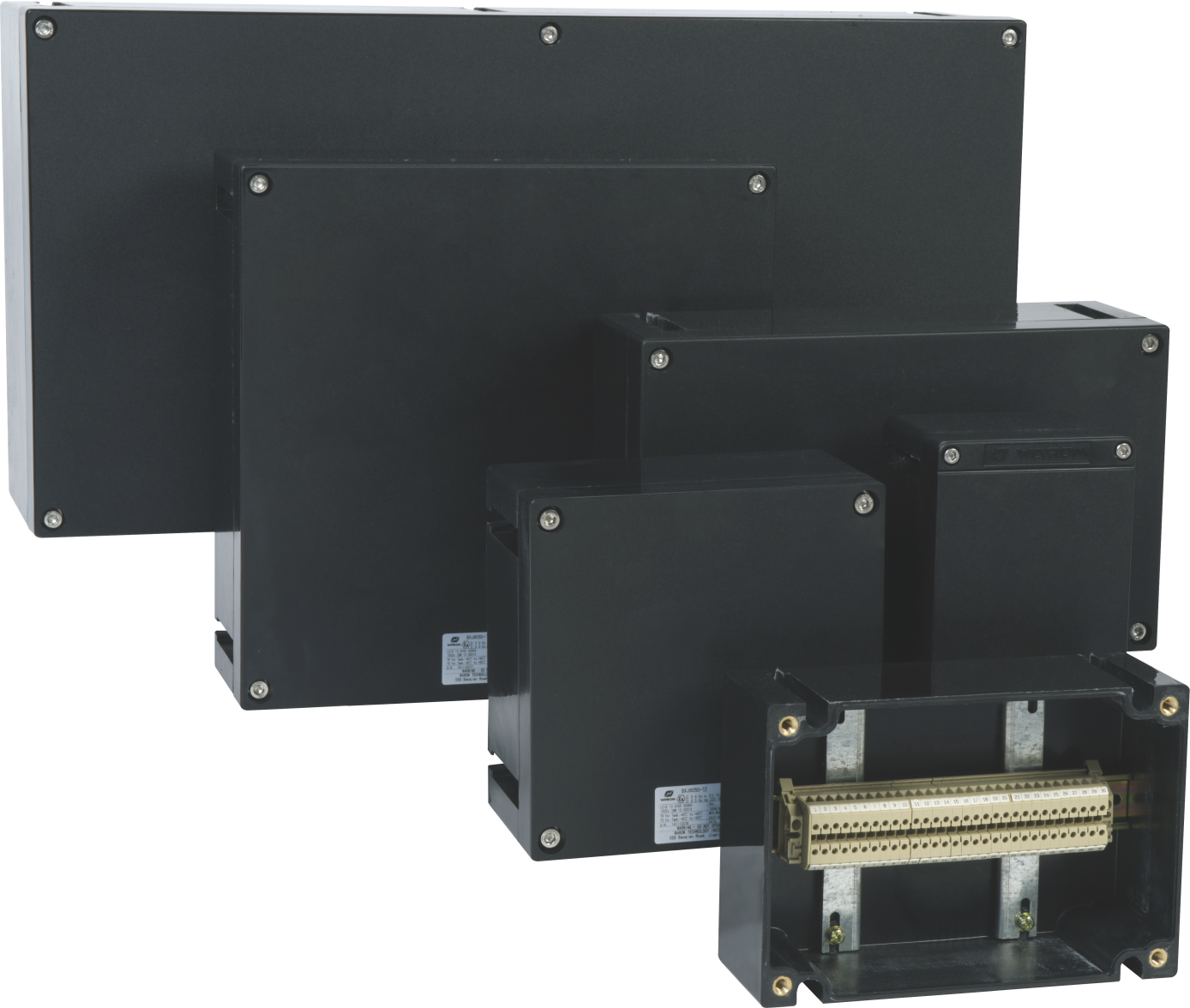
Unarmoured cable is not automatically the easy case. A cable with a filled, gas-tight construction may be acceptable with a certified compression gland, while a similar cable without filling is a candidate for a barrier. That judgement belongs to whoever holds the enclosure certificate and the cable specification, and it is worth settling before the gland order is placed rather than during installation.
Metric and NPT Threads and the Entry They Seal Into
M20 × 1.5 and M25 × 1.5 are the common ISO metric entries on European equipment. NPT entries are tapered: the thread itself forms the seal as it tightens, which is why a metric gland in an NPT hole cannot be made gas tight with tape or sealant. The two forms look similar at a glance and are not interchangeable, and thread adaptors only help when they are covered by the certification.
Three entry details cause most field problems. The first is thread engagement: a thin die-cast wall may not provide enough engaged thread without a boss or a locknut. The second is surface condition, since paint, burrs or corrosion in the entry thread sit exactly where the flame path or seal has to work. The third is the blanking plug, which must be a certified plug of the same thread form, not a plastic shipping cap left in place.
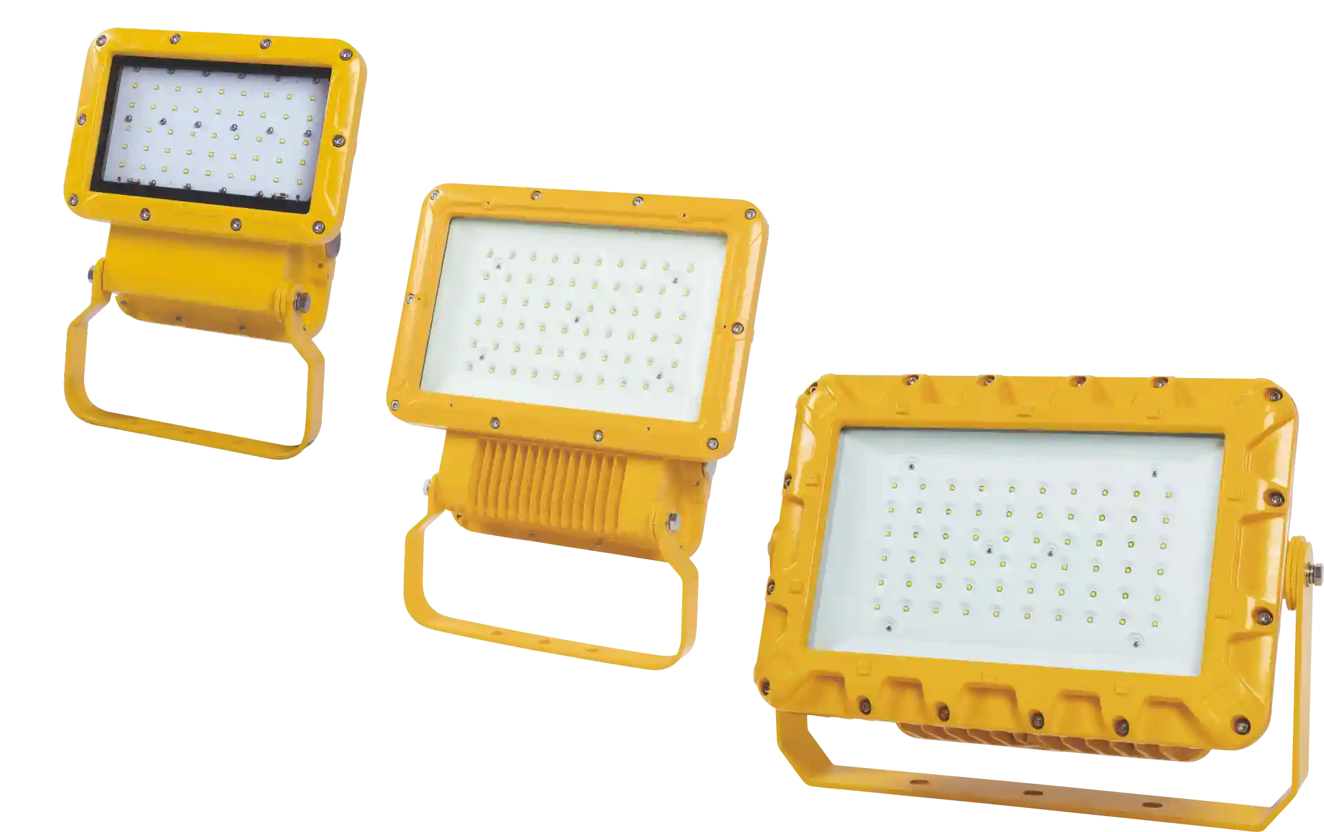
Luminaires show how much the entry schedule matters. A floodlight of this type lists two M25 × 1.5 entries with nickel-plated brass glands recommended for cable from 12.5 to 20.5 mm, so the gland size follows the cable diameter rather than the light fitting. The same logic applies to every powered device on the same rack.
Installation Checks That Keep the Certification Valid
The certificate is a statement about a product. The installation is what an inspector sees years later, and small departures at this stage are what turn a certified assembly into an uncertified one.
- Confirm the gland certificate covers the cable diameter and construction measured on site, not the nominal size on the schedule.
- Inspect each entry before fitting: thread form, burrs, paint, corrosion, and whether the wall gives full thread engagement.
- Fit the body and tighten it to the maker’s stated torque with the correct wrench. Hand tight is not a torque value, and an over-tightened gland distorts the seal.
- Clamp the armour or braid in its cone and check continuity from the armour to the enclosure earth.
- Where a barrier gland is used, mix and pour the compound to the stated level, allow the full cure, and check for voids before the cover goes back on.
- Close every unused entry with a certified plug of the same thread.
- Support the cable so the gland does not carry its weight, and record the gland certificate number, cable diameter, torque, compound batch and installer against the enclosure tag.
Zone 1 installations rarely stop at power and lighting. Transmitters, cameras and warning devices sit on the same structures and go through the same entries, so one entry schedule covering all of them saves a second round of purchasing.
Zone 1 surveillance equipment depends on the same entry discipline as any other powered device in the area. <Explosion-Proof CCTV for Zone 1: Hazardous Area Surveillance> covers camera selection for Zone 1 hazardous areas.
What Goes Wrong Between Inspections
Most gland failures found in service are not product failures. They are installation drift and maintenance drift: a gland that was never torqued, a cable replaced with a different sheath diameter, an adaptor added to solve a thread mismatch, a plug swapped for one from the stores. IEC 60079-17 separates visual, close and detailed inspection, and the difference matters here [8]. A visual inspection sees the gland body, the seal and any corrosion. Confirming compound condition or armour bonding requires opening the enclosure.
| Symptom at inspection | Plausible cause | Next check that distinguishes |
|---|---|---|
| Gland body moves under hand force | Never torqued, or loosened by vibration and thermal cycling | Check torque against the maker’s value and inspect the entry thread for damage |
| Cable slides in the gland | Sheath outside the certified range, or the wrong seal insert fitted | Measure the sheath and compare it with the certificate range |
| Water inside the enclosure | Seal damaged, or an unused entry closed with an uncertified plug | Inspect the seal and every blanking plug |
| White or green deposits at the gland joint | Dissimilar metals in a wet or salt atmosphere | Check the material pair and the finish specified for the site |
| Compound cracked or separated from the cores | Wrong mix ratio, expired compound, or cable movement after cure | Open the enclosure and inspect the seal, then recheck cable support |
| Earth continuity fails at the armour | Armour not clamped, or corrosion under the cone | Test continuity and inspect the cone and the armour contact |
Corrosion deserves its own note. A nickel-plated brass gland in an aluminium enclosure, outdoors on a coastal site, is a galvanic pair. It is a normal combination and it still needs the finish specified for the environment, plus a joint that stays dry. Stainless steel into stainless steel brings a different problem, since dry threads can gall during tightening.
What to Put in an RFQ for Zone 1 Cable Glands
An RFQ that states “M25 glands, 50 off” will produce a quotation for a thread size. Add the area classification, the enclosure certificates and the measured cable data, and the quotation becomes something that can be checked against the installation.
| RFQ field | What to state | Why it matters |
|---|---|---|
| Area classification | Zone 1, gas group IIA, IIB or IIC, and temperature class | Sets the minimum EPL and gas group for the gland |
| Enclosure data | Certificate number and entry thread for each box | The gland has to match the certified entry, not only the thread diameter |
| Cable schedule | Construction, core count, conductor size, measured sheath and inner sheath diameters | Decides the gland size and whether a barrier is needed |
| Protection concept | Ex d, Ex e, or both on the same plant | Decides the gland family and the documentation set |
| Material and finish | Nickel-plated brass, stainless steel or GRP, with coastal or washdown exposure noted | Corrosion and dissimilar metal risk at the joint |
| Documentation | ATEX and IECEx certificates, EU declaration of conformity, torque and installation instructions | Required for the technical file and for later inspection |
Two quotations for the same thread size can differ substantially because one is a barrier gland with compound, a defined cable range and a flameproof certificate, and the other is a general-purpose gland whose thread happens to fit. Compare certificate scopes line by line before comparing price, and treat a missing ambient range or a missing thread form on the certificate as a question rather than a detail.
Send the Entry Schedule Before You Order
Four documents let a supplier match glands to an installation instead of to a thread size: the area classification for each location, the enclosure schedule with certificate numbers and entry threads, the cable schedule with measured diameters, and the protection concept for each area. Warom Technology Incorporated Company builds the DQM-III/II gland family, which holds IECEx TUR 22.0035X and TÜV 22 ATEX 8855X for Ex db IIC Gb in metric and NPT thread from M20 to M115, and can check that family against your entry schedule and return the certificate numbers with the quotation. Email gm*@***om.com or call +86 21 39977076.
FAQ
Can a Zone 2 gland be used in a Zone 1 area?
No. A gland certified for Zone 2 carries EPL Gc, and the certificate says so. Zone 1 needs Gb or higher. The visible difference between two such glands is often only in the seal and the joint, so they look interchangeable on a bench. Check the EPL field and the certificate scope rather than the thread, and confirm the ambient range as well.
Is a barrier gland always required on an Ex d enclosure?
No. It depends on whether gas can travel along the cable core and on what the enclosure manufacturer’s instructions require. A cable with a gas-tight extruded sheath and filled cores may be acceptable with a certified compression gland if the certificate covers that construction. Braided, unfilled and some multi-core armoured cables are the usual candidates for a barrier gland.
Do Ex e enclosures need certified glands?
Yes. The entry is part of the increased safety concept, which depends on the interior staying dry and clean, and on the cable being held mechanically. A general industrial gland with the right thread does not preserve either condition. Check that the gland certificate names Ex e or Ex eb and that its cable range covers the measured sheath diameter.
What does the X at the end of a certificate number mean?
It marks specific conditions of use, which the certificate schedule lists: a cable range, a permitted thread form, a temperature limit, an installation method. The X is not a variant code and not a defect. A gland used outside those conditions is not covered by the certificate, even though the marking on the body is unchanged.
Does an IP66 gland mean it is explosion proof?
No. IP66 describes protection against dust and water jets and says nothing about flame paths or gas containment. Many weatherproof glands reach IP66 without any Ex certification. A certified flameproof gland is usually also rated IP66, which is why both values appear in the same marking string and get read as one claim.
References
[1] IEC 60079-10-1:2020, “Explosive atmospheres. Part 10-1: Classification of areas. Explosive gas atmospheres,” IEC, 2020.
[2] Directive 2014/34/EU of the European Parliament and of the Council on the harmonisation of the laws of the Member States relating to equipment and protective systems intended for use in potentially explosive atmospheres, European Union, 2014. [Online]. Available: https://eur-lex.europa.eu/eli/dir/2014/34/oj
[3] IEC 60079-1:2014, “Explosive atmospheres. Part 1: Equipment protection by flameproof enclosures ‘d’,” IEC, 2014.
[4] IEC 60079-0:2017, “Explosive atmospheres. Part 0: Equipment. General requirements,” IEC, 2017.
[5] IEC 62444:2013, “Cable glands for electrical installations,” IEC, 2013.
[6] IEC 60079-7:2015, “Explosive atmospheres. Part 7: Equipment protection by increased safety ‘e’,” IEC, 2015.
[7] IEC 60079-14:2013, “Explosive atmospheres. Part 14: Electrical installations design, selection and erection,” IEC, 2013.
[8] IEC 60079-17:2013, “Explosive atmospheres. Part 17: Electrical installations inspection and maintenance,” IEC, 2013.
If you’re interested, check out these related articles:
MED ENERGY CONFERENCE & EXHIBITION
Culture casts soul and builds dream with one heart
Chint Group Chairman Nan Cunhui and His Party Visited Warom for Investigation and Exchange
Honor forward – Warom Technology won many awards
Offshore Wind: Explosion Proof Electrical Safety Solutions
With over a decade of experience, he is a seasoned Explosion-Proof Electrical Engineer specializing in the design and manufacture of safety and explosion-proof products. He possesses in-depth expertise across key areas including explosion-proof systems, nuclear power lighting, marine safety, fire protection, and intelligent control systems. At Warom Technology Incorporated Company, he holds dual leadership roles as Deputy Chief Engineer for International Business and Head of the International R&D Department, where he oversees R&D initiatives and ensures the precise delivery of design documentation for international projects. Committed to advancing global industrial safety, he focuses on translating complex technologies into practical solutions, helping clients implement safer, smarter, and more reliable control systems worldwide.

Qi Lingyi