

Explosion proof motor switch faults are rarely random. When a switch fails to operate, trips unexpectedly, or shows corrosion around the cover joint, the cause usually traces to a small group of mechanical and environmental conditions that repeat across plants. The useful approach is to read the failure sequence as a chain: atmosphere enters the enclosure, the flameproof joint deteriorates, the operating mechanism sticks, or the contact surface overheats. I work as an explosion proof electrical engineer at Warom Technology, and the field failures I see most often start at the cable entry, the cover joint, or the actuator seal. Correcting the first failed link in that chain prevents a repeat failure after a new switch is installed.
What Causes Explosion Proof Motor Switches to Fail in the Field?
Most failures start at the boundary between the enclosure and the atmosphere. A flameproof motor switch depends on the machined joint surfaces, often called flame paths, to cool hot gas before it can ignite the surrounding atmosphere. When those surfaces corrode, get scratched, or are reassembled with a damaged gasket, the enclosure can no longer perform that function. The electrical contacts may still work, but the safety function has failed. That distinction matters because a continuity check will miss it.
Warom treats a motor switch fault as electrical, mechanical, or ingress related. Electrical faults include burnt contacts, welded contact tips, broken auxiliary contacts, and overload relay drift. Mechanical faults include a stiff rotary handle, broken return springs, and worn shaft seals. Ingress related faults account for a large share of failures in washdown areas and coastal installations, where water enters through cable glands that were never re-tightened after cable replacement.
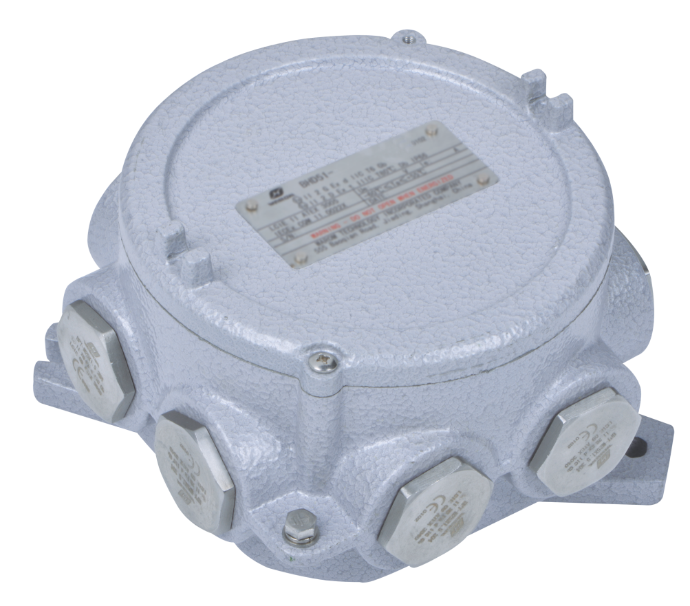
At a chemical plant in Mexico, a site diagnosis found serious electrical safety hazards in an operation with both flammable gas and dust risks. A large share of the risk came from altered cable entries and damaged enclosure joints on existing equipment, not from aging contacts inside the switches. That pattern appears often in small and medium plants: the original installation was sound, but years of gland changes and cover openings changed the protection condition.
Why flameproof integrity fails before the electrical contacts do
Flameproof enclosures do not need to leak to be unsafe. A joint that has been cleaned with a steel wire wheel can lose enough metal to widen the flame path beyond the certified gap. The same is true when a cover is dropped and refitted without checking for a raised edge. We see this after a plant shutdown, when maintenance crews are under time pressure. The switch passes a functional test, but the explosion protection rating is no longer valid.
Why motor switch faults follow the installation environment
A switch mounted outdoors on a chemical dock faces a different failure chain than one inside a dry motor control room. Salt, wet hydrogen sulfide, ammonia, and solvent vapor each attack different materials. Aluminum enclosures can corrode around stainless steel bolts in a marine atmosphere. Polyester enclosures resist corrosion but need UV stable seals over long outdoor exposure. Matching the enclosure material to the environment at the start removes a fault source that no amount of troubleshooting will fix.
How Do You Troubleshoot an Explosion Proof Motor Switch Without Creating an Ignition Risk?
The first rule is that an explosion proof enclosure is only explosion proof when it is complete, undamaged, and correctly assembled. If the switch is live, do not open it. If the atmosphere may be present, do not open it even with the circuit de-energized until a gas test has confirmed the area is clear. On a gas processing or solvent handling site, this usually means a hot work permit or an inspection permit controlled by operations. The switch label will state the zone or division, gas group, temperature class, and certificate reference. Work only within those limits.
Before opening, record the visible condition of the cover joint, the cable glands, and the actuator. Look for paint blisters, white corrosion product, cracks, or a cover that moves slightly when pressed. These observations are the best early clues. On field checks after cable replacement, loose glanding is the single most common defect I find. A cable gland that has been hand tightened instead of torqued to the manufacturer’s value lets water run down the cable into the enclosure.
Water ingress remains one of the most common reasons an explosion proof motor switch shows internal rust or nuisance trip faults. <IP64 Rating Guide: Practical Device Protection Tests> explains how a practical IP64 verification differs from a simple spray test and why the sequence matters for enclosures that are opened repeatedly.
Once the gas test is clear, isolate and lock out the circuit, verify the absence of voltage, and then open the enclosure. Never force a stuck cover. If the cover does not release, stop and inspect whether a bent flange or a swollen gasket is holding it. Forcing the cover can score the flame path, and the resulting repair is often more expensive than a replacement switch.
Inside, photograph the terminal area before disturbing any wiring. Check terminal screws for signs of heat, such as darkening of the wire insulation or discoloration of the metal. Check the internal earth connection and any bonding conductors. On motor switches with a rotary operator, work the handle across its full travel and listen for a clean detent. A soft or gritty feel usually points to a broken spring or worn cam.
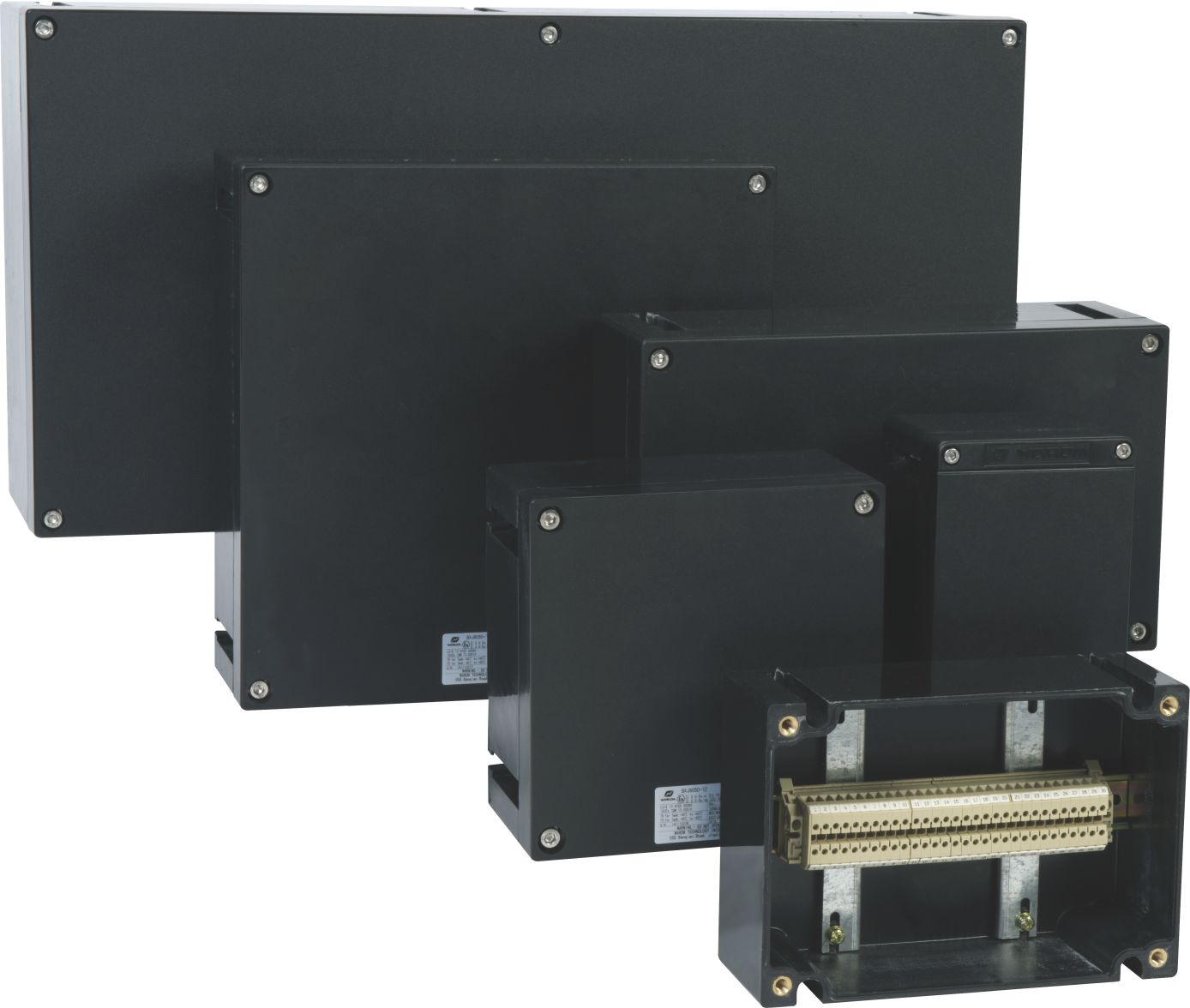
Insulation resistance testing, contact resistance checks, and protective bonding continuity are useful only when the enclosure is open and the area has been confirmed safe. Compare the results with the previous maintenance record. A single low insulation value may be moisture. A steadily falling trend across several tests points to aging insulation or repeated condensation.
Which Fault Patterns Show Up Most Often in Explosion Proof Motor Switches?
Most motor switch failures I see in the field fall into four groups: the switch does not operate, the switch operates but does not latch, the switch trips or drops out under load, and the enclosure shows visible damage or water. The table below separates the symptom from the likely cause and the first check.
| Symptom | Likely cause | First check |
|---|---|---|
| Handle is stiff or locked | Broken return spring, corroded shaft, swollen seal | Operator mechanism and shaft seal |
| Switch does not latch in the ON position | Worn latch or damaged cam | Mechanical latching assembly |
| Terminals show heat discoloration | Loose terminal torque or high resistance joint | Torque setting and contact surface |
| Nuisance trip during motor start | Overload relay mis-set or single-phase condition | Relay setting against motor nameplate |
| Internal rust or water marks | Cable gland not tightened, damaged gasket | Gland installation and cover joint |
In a flameproof switch, the latching problem deserves extra attention. A switch that refuses to latch should be isolated and inspected, not forced. Some operators add a temporary tie or wedge to keep the handle engaged. That defeats the mechanical interlock and the explosion protection function, and I would reject the installation immediately.
Single phasing is another frequent root cause that gets blamed on the switch. The switch may open correctly when a motor winding has failed or one phase has been lost. Replacing the switch does not fix the missing phase. The right check is to measure the incoming and outgoing phase voltages during the start sequence, after the area has been confirmed safe.
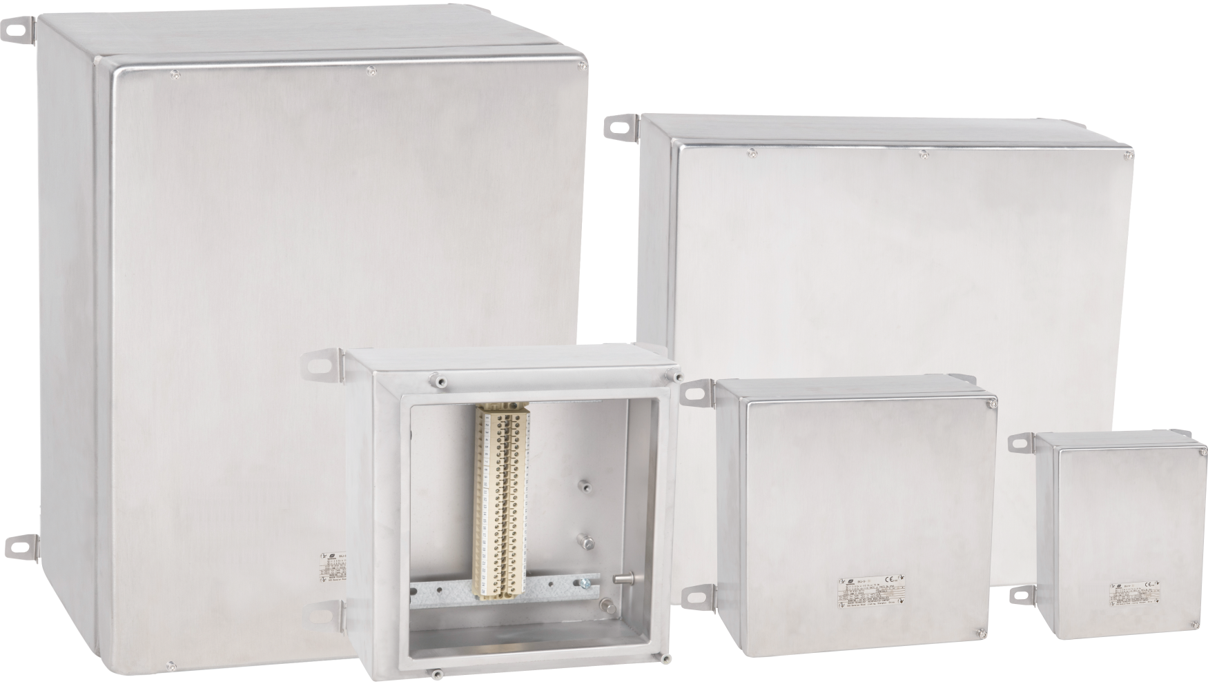
Coastal and marine installations add a corrosion failure mode that inland sites rarely experience. <Stainless Steel Explosion Protection for Marine Electrical Systems> covers why stainless steel flameproof enclosures resist salt driven pitting better than aluminum and what to specify when a switch must survive repeated washdown exposure.
If your site has a mix of switches from different projects, the nameplate alone may not tell you whether the flame path is within tolerance. Before finalizing your bill of materials, confirm the certificate and the permitted joint gap against the manufacturer’s data. Send the nameplate photo and the fault detail to gm*@***om.com or call +86 21 39977076 for a quick check.
When Should You Replace an Explosion Proof Motor Switch Instead of Repairing It?
Replace the switch when flameproof integrity cannot be restored to the certified condition. In practice, that means any of these conditions: the flame path is pitted or scratched beyond the manufacturer’s allowable repair depth; the enclosure has cracks, dents, or a distorted flange; the actuator shaft is visibly worn; or the contact carrier is burnt or melted. Repainting the outside does not restore a damaged joint. In a Zone 1 or Division 1 area, a switch that no longer meets the original protection concept is not a minor defect; it is a nonconformity.
Some switches can be repaired with manufacturer supplied contact kits, seals, and operating mechanisms. The decision depends on age, parts availability, and whether the repair facility is authorized for explosion protected equipment work. If the local workshop cannot machine the flame path back within tolerance, do not attempt a field repair. Replacement is the lower cost option.
Also replace when the marking is illegible. An explosion proof motor switch without a readable certificate reference cannot be selected or installed for a hazardous area. If the nameplate is damaged, the compliance history becomes unverifiable. This is a common finding on older plants, and it is a valid reason to stop using the switch until the manufacturer confirms the model and certification.
On the Tilenga project in Uganda, Warom supplied explosion proof electrical systems for wellpads, a central processing facility, and pipelines, some within Murchison Falls National Park. The environment demanded zero safety incidents under extreme conditions. That project reinforced a simple rule: replacement decisions should be based on whether the equipment can still meet the certified protection condition in that environment, not on whether it still switches.
What Information Do We Need to Diagnose Your Explosion Proof Motor Switch?
When an explosion proof motor switch fails, the fastest path to a correct replacement is to send the nameplate photo, the observed symptom, and the environment where the switch is installed. A fault described only as ‘switch not working’ gives us no basis to separate a mechanical latch failure from a burnt contact or a moisture problem. The enclosure condition matters as much as the electrical symptom. If you can include a photo of the cable entries and the cover joint, the diagnosis moves faster.
For our service team, the goal is to match the replacement to the existing protection concept, certificate, and cable entry arrangement, not simply to change the part. We review the switch rating against the zone or division, gas group, temperature class, and IP rating before quoting anything. Send the switch nameplate, the fault description, and the site voltage to gm*@***om.com, or call +86 21 39977076 or +86 21 39972657. We will confirm whether the switch should be repaired, replaced with the same rating, or reviewed as part of a larger enclosure remediation.
What Other Explosion Proof Motor Switch Questions Come Up in Service?
Can I open an explosion proof motor switch for inspection while the circuit is de-energized?
Only if the area has been confirmed gas free and the circuit is locked out. Opening a flameproof enclosure in a hazardous atmosphere is not permitted, even with power off, because the cover joint is the protection and the act of opening it can release hot internal surfaces or sparks from a defective component. Once the gas test is clear and absence of voltage is verified, open the cover and inspect the joint. Afterward, torque the cover to the manufacturer’s value using the correct fastener sequence. A switch reassembled with missing bolts has no protection rating.
Why does the switch trip only when the motor starts under full load?
A trip at start is often blamed on the motor switch contacts, but the overload relay setting is usually the first thing to check. If the relay is set too close to the locked rotor current, the normal start inrush will trip it. Compare the relay setting with the motor nameplate and the actual start duty: a fan or conveyor starting under load needs a setting that accounts for the acceleration time, while a direct online pump may be fine. Single phasing and low supply voltage at the starter terminals produce the same symptom, so confirm the incoming voltage before replacing the switch.
What does it mean if the switch cover is warm to the touch?
It depends on the location and the temperature. A warm cover near the cable entry or terminals can be normal when the switch carries load, but a hot spot that develops quickly, smells burnt, or discolors the finish is a sign of a loose connection. For a flameproof enclosure, the external surface temperature is limited by the temperature class. If the switch runs at the upper end of its rating, check the enclosure with the correct measuring equipment before continuing.
Is it acceptable to use a standard industrial motor switch inside a purged enclosure?
The better question is what protection concept applies to the complete assembly. A standard industrial motor switch inside a purged enclosure can be acceptable if the purge system is designed and certified for that arrangement, but it is not an explosion proof switch. The motor circuit still depends on the purge system operating correctly before power is applied. In a Zone 1 or Division 1 area, this is usually a more complex design than a direct flameproof switch. Review the assembly certificate and the pressure loss alarm before deciding.
How long does a replacement explosion proof motor switch usually take to ship?
In our project work, the lead time depends more on the certification and cable entry configuration than on the switch frame. Standard IECEx or ATEX certified motor switches can usually ship quickly when the current rating, enclosure material, cable entries, and auxiliary contacts are stock items. Custom entries or a specific temperature class may add several weeks. We check the exact nameplate against the available certificates before quoting a date, because a switch that looks identical from the outside can have a different flame path and approval. Share your switch nameplate and operating voltage, and we will confirm the documentation and lead time before you commit.
If you’re interested, check out these related articles:
Warom 2024 International IECEx Explosion-Proof Technology Malaysia Seminar was successfully held
Pendant Light Fittings: Essential Safety for Hazardous Areas
Explosion Proof AC for 50°C: Extreme Heat Solutions
The New Factory of WAROM MENA
Warom Spring Festival Groundbreaking Ceremony
With over a decade of experience, he is a seasoned Explosion-Proof Electrical Engineer specializing in the design and manufacture of safety and explosion-proof products. He possesses in-depth expertise across key areas including explosion-proof systems, nuclear power lighting, marine safety, fire protection, and intelligent control systems. At Warom Technology Incorporated Company, he holds dual leadership roles as Deputy Chief Engineer for International Business and Head of the International R&D Department, where he oversees R&D initiatives and ensures the precise delivery of design documentation for international projects. Committed to advancing global industrial safety, he focuses on translating complex technologies into practical solutions, helping clients implement safer, smarter, and more reliable control systems worldwide.

Qi Lingyi