

Explosion proof vibration sensors for Zone 2 rotating machinery do not need the same protection concept as a Zone 0 gas detector, but that difference still causes specification errors. I have seen pump and compressor packages specified with intrinsically safe sensors and multiple isolators when a certified Ex nA loop-powered accelerometer would have matched the area classification at lower cost and with simpler maintenance. The correct selection starts with the protection concept and the signal path, not the sensor housing alone. This article sets out what to confirm before the loop goes into a pump, fan, compressor, or gearbox.
What Makes Zone 2 Vibration Sensor Selection Different?
Zone 2 is not a milder label. IEC 60079-10-1 defines it as a location where a flammable gas or vapor is not expected in normal operation and, if it does appear, it lasts only for a short period. That changes the equipment requirement. The instrument should not create an ignition source during normal service; it does not have to contain an internal explosion the way Ex d flameproof equipment does. For a vibration loop on a bearing housing, this means Ex nA, Ex ic, or Ex ec concepts are often technically valid where an Ex d housing would be overspecified.
The selection error I see most often is treating Zone 2 as a low-risk afterthought and asking only for an Ex marking. The sensor still includes electronics and cable terminations that can become ignition sources if the installation is not controlled. The gas group and temperature class still matter. A hydrogen compressor area may require IIC while a propane pump area may only require IIA or IIB. If the inquiry says only “Zone 2 vibration sensor”, the quote will be ambiguous. Ask for the protection concept, the EPL, the gas group, and the temperature class.
What Certification Markings Do Explosion Proof Vibration Sensors Need?
When I review a vendor quote, I look first at the marking, not the brochure. A Zone 2 sensor should carry an ATEX Category 3 G marking for European projects, an IECEx marking for international work, or the North American Division 2 nonincendive path where local codes require it. A typical marking is Ex nA IIC T4 Gc. The IIC shows the gas group capability, T4 limits the surface temperature to 135°C, and Gc is the EPL for Zone 2. A sensor marked Ex ic IIC T4 Gc is energy-limited and may need a barrier. A sensor marked Ex nA IIC T4 Gc is non-sparking and usually runs on a standard 4-20 mA loop.
Buyers should also request the certificate number and the conditions of safe use. Some Ex nA designs have a restriction against connection or disconnection while energized. That restriction changes commissioning and live maintenance.
The table below is the quick check I use.
| Protection concept | Typical marking | Practical note for rotating machinery |
|---|---|---|
| Ex nA non-sparking | Ex nA IIC T4 Gc | No sparking contacts in normal operation; fits most loop-powered velocity and acceleration transmitters. |
| Ex ic intrinsic safety | Ex ic IIC T4 Gc | Energy-limited circuit; verify barrier parameters and cable capacitance. |
| Ex ec increased safety | Ex ec IIC T4 Gc | Terminal and gland discipline decide compliance; suits wiring boxes and remote terminations. |
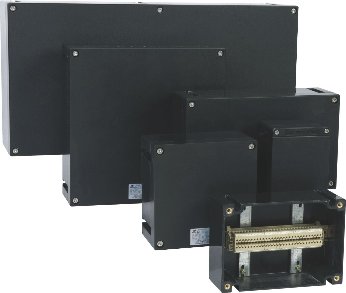
Where the sensor wires land in a local marshalling box, that box carries the same Zone 2 responsibility as the sensor.
Which Output and Installation Details Keep the Loop Reliable?
The sensor output decides what the plant can do with the signal. A 4-20 mA transmitter proportional to RMS velocity is the most practical option for a pump or fan. It connects directly to a DCS or PLC analog input, handles long cable runs better than a raw accelerometer signal, and fits Ex nA or Ex ic loops with fewer interface components. An IEPE accelerometer gives high-frequency data for gear mesh and bearing defect analysis, but it needs a conditioning module near the sensor or a dedicated monitor. If the application needs both simple alarm and diagnostic data, check whether the unit offers a raw dynamic output alongside the loop signal.
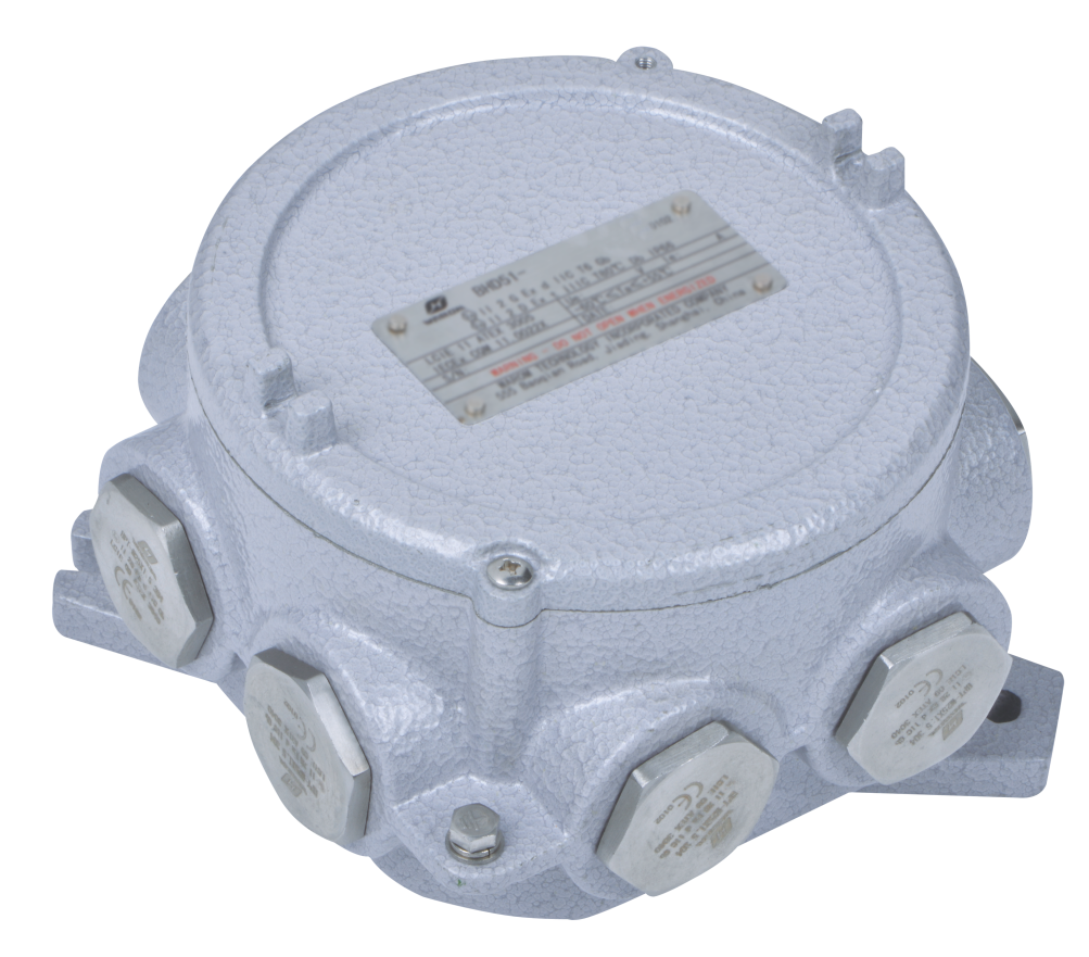
Installation determines whether the certification remains valid. The cable gland must match the cable outer diameter and the sensor entry thread. The screen should be earthed at one point only so that low-frequency ground-loop noise does not enter the measurement. If the sensor wiring enters a local junction box, that enclosure must be rated for the zone. In many projects, the junction box is where wiring errors appear, not the sensor itself. A BHD91 series junction box with IP66 sealing and certified cable glands such as DQM-III is one configuration we use, but the gland selection must follow the actual cable.
Vibration data covers the mechanical condition of the machine, but the motor electrical protection remains separate. <Explosion-Proof DOL Motor Starters: Essential Specifications and Selection> covers thermal overload settings and why DOL starters remain the practical choice for many fixed-speed Zone 2 drives.
If the loop passes through a shared hazardous-area junction box or uses armored cable with multiple screens, confirm the gland and earthing arrangement before locking the bill of materials. Send the loop drawing and zone classification to gm*@***om.com.
How Do Vibration Sensors Feed Rotating Machinery Monitoring?
A vibration sensor is not a protection relay. It produces trend data that lets the maintenance team act before a bearing defect reaches a forced outage. In a typical installation, the 4-20 mA signal goes into a DCS or condition monitor, and alarms are set on overall velocity. The first sign of many bearing and misalignment faults is a rising overall level, not a temperature rise. By the time the bearing temperature alarm appears, the damage is usually advanced.
Vibration data is more useful when it is tied to machine state. A sensor that only trends a level while the pump runs at changing speeds may create false alarms. In those cases, the monitor should gate the vibration value to speed or load, or the sensor should feed a system that stores waveform data for review.
In a typical direct-on-line machine, the condition monitor and the motor protection have different jobs. Vibration detects the mechanical fault; the starter clears the electrical fault. Keeping those functions separate reduces wiring complexity and keeps the vibration loop focused on condition data.
What Should You Send Before Ordering Zone 2 Vibration Sensors?
Specifying a Zone 2 vibration sensor from a catalog line item rarely produces a clean quotation. The supplier needs the gas group, temperature class, installation layout, cable type, and output signal before they can confirm the protection concept. If those details are missing, the buyer receives either an overpriced Ex d unit or a sensor with the wrong marking for the area.
Before ordering, send the hazardous area classification drawing, the sensor location list, and the electrical loop detail. State whether the machine runs continuously or intermittently, and whether the vibration value goes to a DCS, a local PLC, or a portable monitor. Include the cable type and gland entry. Our engineers will confirm the Ex nA, Ex ic, or Ex ec path, the gland selection, and the interface wiring. Email gm*@***om.com or call +86 21 39977076 or +86 21 39972657.
What Do Maintenance Teams Ask Before Specifying Zone 2 Vibration Sensors?
Can we install a standard industrial vibration sensor in Zone 2?
No. A standard sensor may be sealed against dust and water and still have no certified protection concept such as Ex nA, Ex ic, or Ex ec. Zone 2 is not only about sealing; the equipment must be marked for the area and installed under IEC 60079-14. A stainless housing does not make an instrument zone-rated. If the sensor is already installed, check the certificate before using it in a classified location.
Does Zone 2 require an intrinsically safe vibration sensor?
Not in most cases. Ex ic intrinsic safety is one acceptable path, but Ex nA and Ex ec are also permitted for many Zone 2 applications. The choice depends on the loop. If the sensor connects directly to a DCS analog card without a barrier, an Ex nA or Ex ec transmitter is often simpler. Intrinsic safety becomes useful where maintenance teams need to connect and disconnect a portable monitor in the field, because the energy is limited at the source.
What is the difference between Zone 2 and Class I Division 2?
They describe similar risk levels but use different systems. Zone 2 belongs to the IEC and ATEX framework for an area where flammable gas is not normally present. Class I Division 2 is the North American NEC counterpart. The markings and certificate structures differ, so equipment approved under one system is not automatically acceptable under the other. For international work, confirm which standard the local authority accepts before ordering.
How often should a Zone 2 vibration sensor be checked?
The certification is not a wearable part, but the installation belongs in the normal hazardous-area inspection route. We check gland tightness, cable condition, and the earthing path, then verify the loop signal against a reference shaker or simulator. In a corrosive or high-vibration location, shorten the interval. If the plant uses an asset management route, add the vibration loop check to it. If the existing loop drawing is unclear, share it with gm*@***om.com and we will confirm the barrier or isolator requirement before you order.
If you’re interested, check out these related articles:
Warom at 40th ADIPEC 2024
Explosion Proof Floodlights for Hazardous Industrial Areas
Industrial Lighting Color Temperature: A Complete Guide
Explosion Proof Solutions for Coal Conveyor Safety
With over a decade of experience, he is a seasoned Explosion-Proof Electrical Engineer specializing in the design and manufacture of safety and explosion-proof products. He possesses in-depth expertise across key areas including explosion-proof systems, nuclear power lighting, marine safety, fire protection, and intelligent control systems. At Warom Technology Incorporated Company, he holds dual leadership roles as Deputy Chief Engineer for International Business and Head of the International R&D Department, where he oversees R&D initiatives and ensures the precise delivery of design documentation for international projects. Committed to advancing global industrial safety, he focuses on translating complex technologies into practical solutions, helping clients implement safer, smarter, and more reliable control systems worldwide.

Qi Lingyi